Roof mounted antenna for recreational vehicles and the like

a technology for recreational vehicles and antennas, applied in the direction of resonant antennas, substantially flat resonant elements, wind-induced force reduction, etc., can solve the problems of roof antenna damage, risk of damage or even removal, etc., and achieve the effect of simplifying the installation of the antenna assembly

Active Publication Date: 2020-12-31
STEINER ENTERPRISES
View PDF0 Cites 0 Cited by
  • Summary
  • Abstract
  • Description
  • Claims
  • Application Information

AI Technical Summary

Benefits of technology

[0004]A cover is attached to the body to complete enclose the planar antenna structure. The cover includes a flange extending from a bottom surface of the cover for engagement within a complementary opening in the roof of the vehicle, to simplify the installation of the antenna assembly. The flange defines an opening to permit connection of TV cables from the vehicle with electrical terminals.
[0005]The body has a shark fin configuration with an angled leading edge and a low lateral profile. The body configuration helps the antenna assembly to resist contact with low-hanging foliage that the vehicle may drive under. The profile helps push the foliage aside without damaging the planar antenna inside.

Problems solved by technology

However, one detriment to the roof-mounted antenna is that it is at risk of damage or even removal by contact with low hanging foliage.

Method used


Image

  • Roof mounted antenna for recreational vehicles and the like
  • Roof mounted antenna for recreational vehicles and the like
  • Roof mounted antenna for recreational vehicles and the like

Examples


Embodiment Construction

[0011]For the purposes of promoting an understanding of the principles of the disclosure, reference will now be made to the embodiments illustrated in the drawings and described in the following written specification. It is understood that no limitation to the scope of the disclosure is thereby intended. It is further understood that the present disclosure includes any alterations and modifications to the illustrated embodiments and includes further applications of the principles disclosed herein as would normally occur to one skilled in the art to which this disclosure pertains.

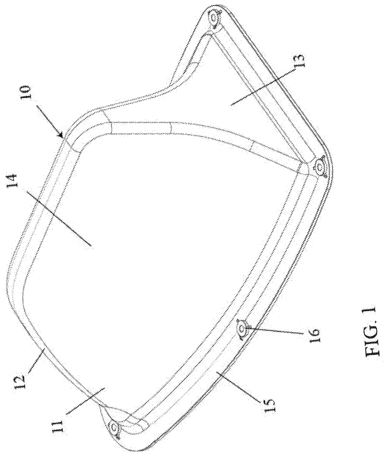
[0012]An antenna assembly 10 shown in FIG. 1 incorporates a “shark fin” configuration in its body 11. In particular, the body 11 is a hollow shell that houses and protects the working components of the antenna assembly. The body includes a leading edge 12 that is angled rearwardly when mounted on the roof of a vehicle, such as an RV. In particular, the assembly is mounted on the vehicle roof with the leading...


PUM


Abstract

An antenna assembly for mounting on the roof of a recreational vehicle includes a planar antenna structure configured to receive UHF/VHF signals and a shark fin shaped body sized to surround the planar antenna structure vertically oriented relative to the vehicle. The body includes a mounting flange adapted to be fastened to the roof of the vehicle, and a cover attached to the body to completely enclose the planar antenna structure. The cover includes a flange extending from a bottom surface of the cover for engagement within a complementary opening in the roof of the vehicle. The antenna structure includes a printed circuit board with electrical terminals extending therefrom into the flange for connection to TV cables of the vehicle.

Description

PRIORITY CLAIM[0001]This application is a utility filing of and claims priority to co-pending U.S. provisional application No. 62 / 867,934, filed on Jun. 28, 2019, the entire disclosure of which is incorporated herein by reference.BACKGROUND[0002]Many recreational vehicle owners and users enhance their traveling experience with television and radio. Consequently, the RV roof-mounted antenna market has grown considerably over the years. However, one detriment to the roof-mounted antenna is that it is at risk of damage or even removal by contact with low hanging foliage. Roof mounting is necessary to provide adequate signal reception for the television or radio within the RV. There is a need for an antenna that is easily mounted on the roof of an RV and that can withstand the forces from the occasional contact with trees and other foliage.SUMMARY OF THE DISCLOSURE[0003]An antenna assembly for mounting on the roof of a vehicle includes a planar antenna structure configured to receive UH...

Claims


Application Information

Patent Timeline
Patent Type & Authority Applications(United States)
IPC IPC(8): H01Q1/32H01Q1/12H01Q9/04
CPCH01Q1/12H01Q1/3275H01Q9/0407H01Q1/42H01Q1/005
Inventor HICKS, THOMAS P.DEWITT, DONALD E.DEWITT, JOSHUA E.
Owner STEINER ENTERPRISES
Why Eureka
Try Eureka