
Mechanical-stress sensor and manufacturing method

a technology of stress sensor and manufacturing method, which is applied in the direction of force measurement, instruments, force measurement, etc., to achieve the effect of high reliability of operation, simple and inexpensive manufacturing

Pending Publication Date: 2020-12-31
ELTEK
View PDF0 Cites 1 Cited by
  • Summary
  • Abstract
  • Description
  • Claims
  • Application Information

AI Technical Summary

Benefits of technology

The present invention provides a simple and inexpensive mechanical-stress sensor with high reliability of operation. This is achieved by a mechanical-stress sensor and a manufacturing method with the characteristics described in the claims.

Problems solved by technology

Notwithstanding their wide diffusion, some piezoelectric sensors, in particular those for detecting shear stresses, still present some drawbacks, which are linked, for example, to their manufacturing modalities.

Method used


Image

  • Mechanical-stress sensor and manufacturing method
  • Mechanical-stress sensor and manufacturing method
  • Mechanical-stress sensor and manufacturing method

Examples


Embodiment Construction

[0031]Reference to “an embodiment”, “one embodiment”, “various embodiments”, and the like, in the framework of the present description is intended to indicate that at least one particular configuration, structure, or characteristic described in relation to an embodiment is comprised in at least one embodiment. Hence, phrases such as “in an embodiment”, “in one embodiment”, “in various embodiments”, and the like that may be present in various points of this description do not necessarily refer to one and the same embodiment, but may, instead, refer to different embodiments. Moreover, particular conformations, structures, or characteristics defined in the framework of the present description may be combined in any adequate way in one or more embodiments, which may even be different from the ones shown. The reference numbers and spatial references (such as “top”, “bottom”, “up”, “down”, “front”, “back”, “vertical”, etc.) provided herein, in particular with reference to the examples in ...


PUM

PropertyMeasurementUnit
thicknessaaaaaaaaaa
thicknessaaaaaaaaaa
thicknessaaaaaaaaaa

Abstract

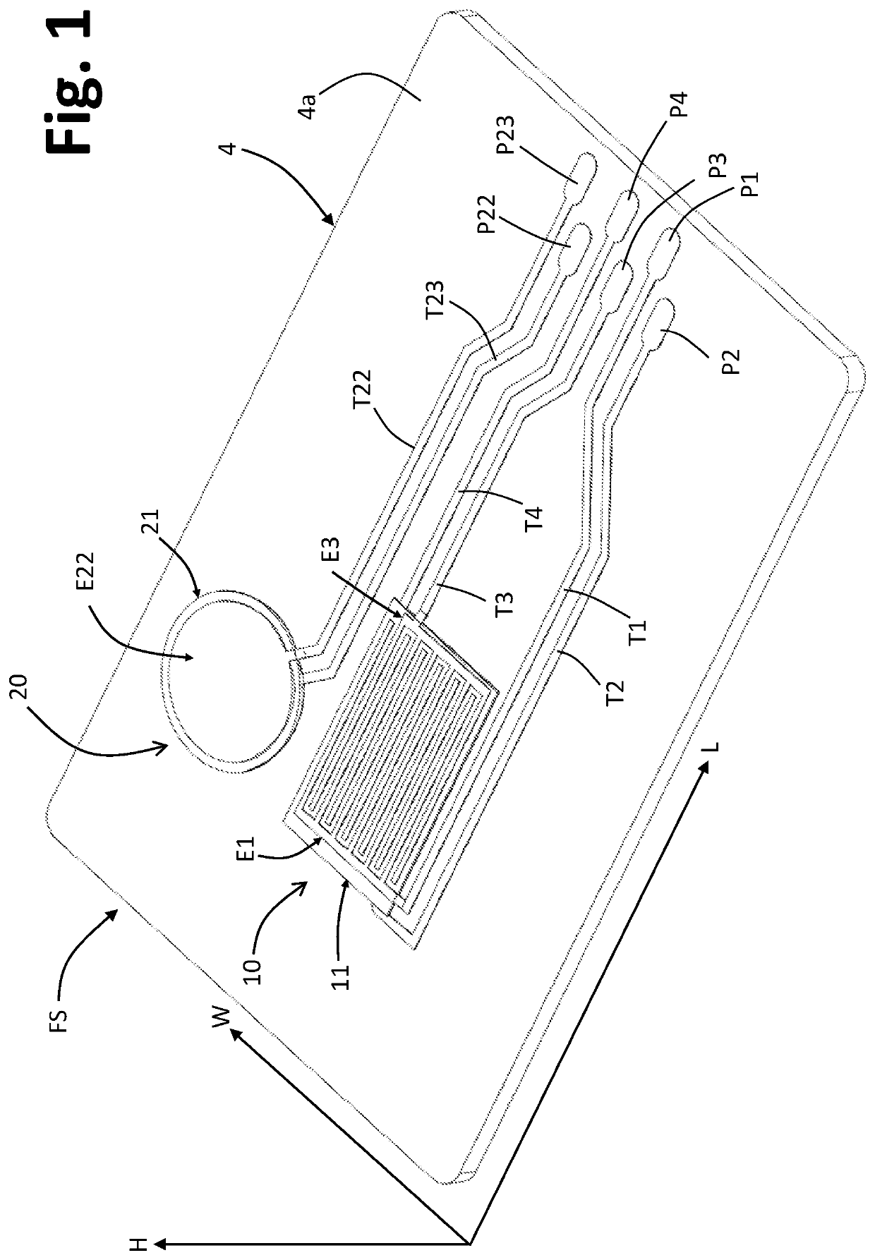
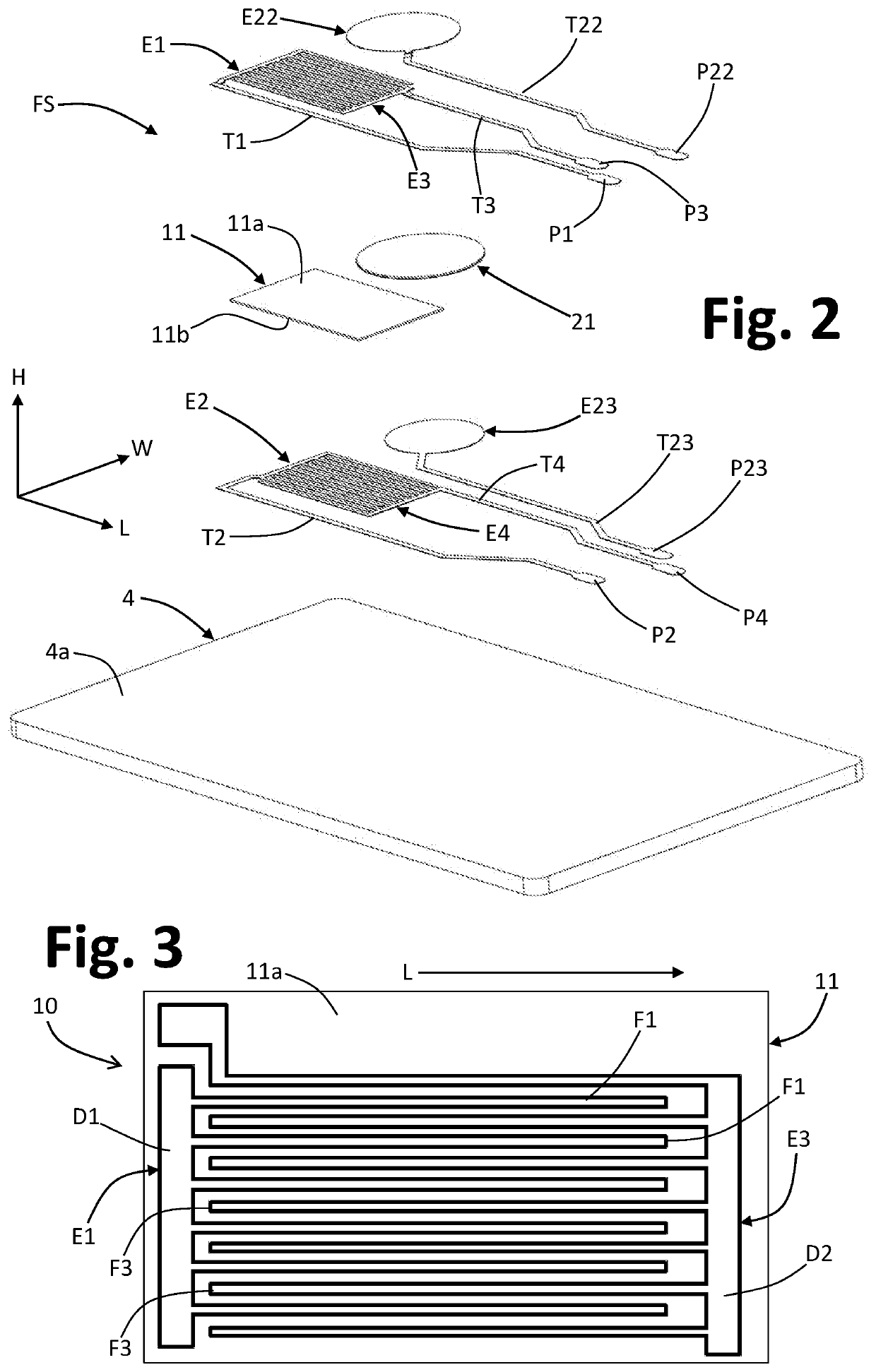
A mechanical-stress sensor comprises a piezoelectric transducer (10), which is able to generate an electrical signal representing a shear stress. The piezoelectric transducer (10) comprises: a layer of piezoelectric material (11), which extends in a longitudinal direction and has a polarization axis (A), which extends in a direction transverse to the longitudinal direction; and at least one first electrode (E1) and one second electrode (E2), each having a plurality of fingers (F1, F2), which extend at a first major face and a second major face, respectively, of the layer of piezoelectric material (11). The piezoelectric transducer (10) comprises at least one third electrode (E3) and one fourth electrode (E4), each having a plurality of fingers (F3, F4), which extend at the first major face and second h major face, respectively, of the layer of piezoelectric material (11), the fingers (F3) of the third electrode (E3) being interdigitated or alternating with the fingers (F1) of the first electrode (E1), and the fingers (F4) of the fourth electrode (E4) being interdigitated or alternating with the fingers (F2) of the second electrode (E2).

Description

FIELD OF THE INVENTION[0001]The present invention relates to mechanical-stress sensors and has been developed with particular reference to stress sensors of a piezoelectric type and to the modalities for manufacture thereof.PRIOR ART[0002]The use of piezoelectric stress sensors is widely known for detecting transverse (shear) stresses or normal or axial (compressive) stresses. Such sensors are, for example, used for providing acceleration sensors, pressure sensors, vibration sensors, deformation sensors, and so forth. Also the specific applications and the industrial sectors of use of the sensors referred to are extremely varied, and include the vehicle sector (e.g., for providing impact sensors or sensors for detecting engine knock), the consumer-electronics sector (e.g., for providing touch input devices or devices for measuring consumption of ink by printer cartridges), the medical sector (e.g., for providing of cardiovascular sensors), the building sector (e.g., for providing st...

Claims


Application Information

Patent Timeline
Patent Type & Authority Applications(United States)
IPC IPC(8): G01L1/16G01L5/167
CPCG01L1/162G01L5/167G01L1/16
Inventor PIZZI, MARCOALLERA, STEFANO
Owner ELTEK
Learn More