Flow control device and method
a flow control and conduit technology, applied in the direction of sealing/packing, wellbore/well accessories, instruments, etc., can solve the problems of increasing the ability, reducing the degree of production, so as to avoid excessive protrusion, increase production cost, and increase the degree of production
- Summary
- Abstract
- Description
- Claims
- Application Information
AI Technical Summary
Benefits of technology
Problems solved by technology
Method used
Image
Examples
Embodiment Construction
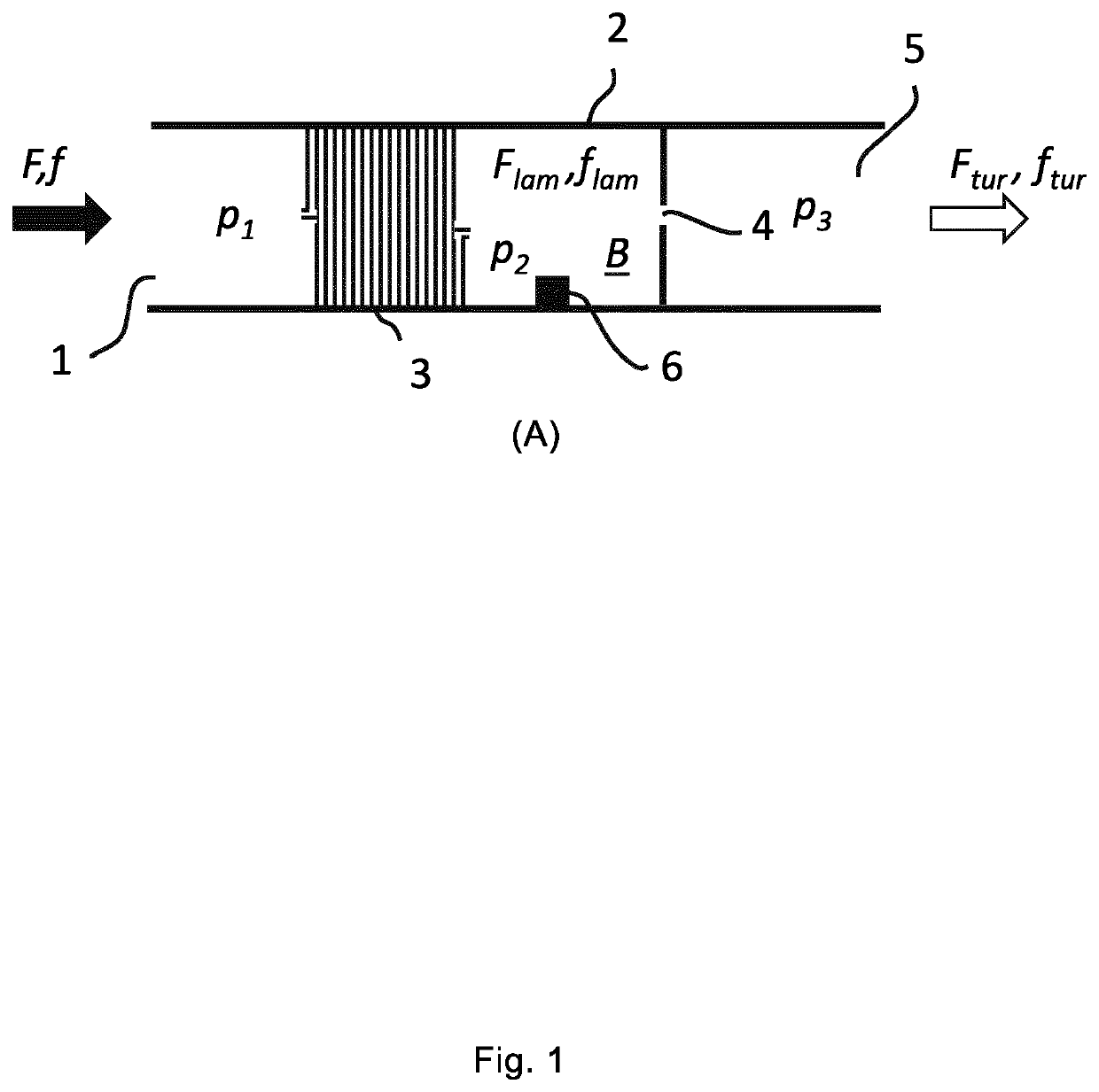
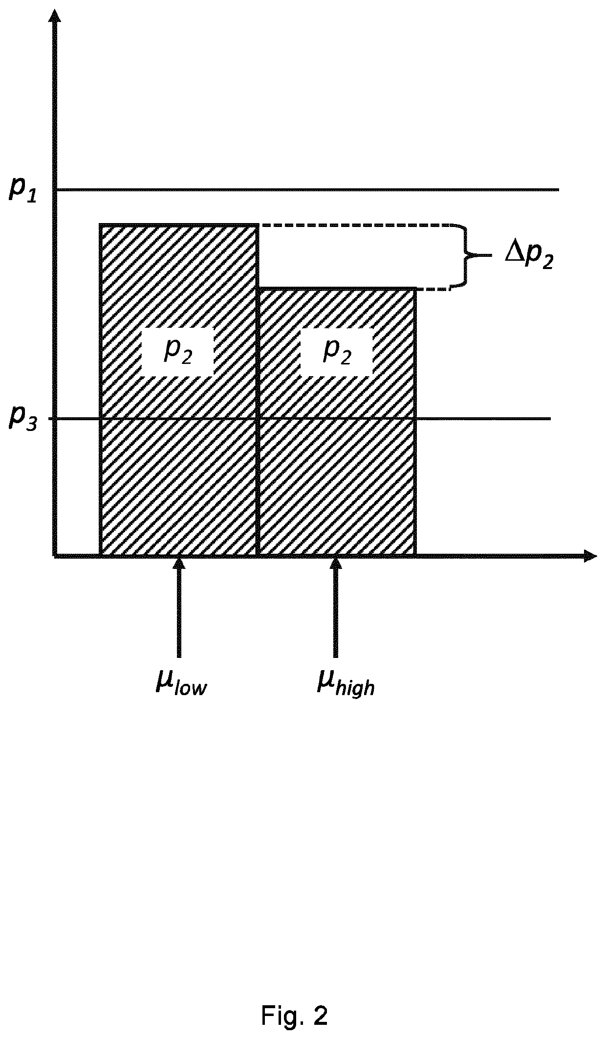
ates how a fluid F,f flows through a fluid flow inlet 1 into a conduit 2 at a first pressure p1, further through a first fluid flow restrictor 3 and into a chamber B where it attains a second pressure p2, and then flows through a second fluid flow restrictor 4 before it exits the conduit 2 through a fluid flow outlet 5 at a third pressure p3. When the fluid flow rate and fluid properties (e.g. viscosity, density) are kept constant, the pressures (p1, p2, p3) are also constant, and p1, >p2, >p3.
[0082]In FIG. 1, the first fluid flow restrictor 3 is a coiled pipe and the second fluid flow restrictor 4 is an orifice. The coiled pipe may have any cross-sectional shape such as circular shape, rectangular shape, triangular shape, etc.
[0083]In general, the pressure loss due to viscous effect in a cylindrical pipe of length L and uniform diameter D is proportional to length L and can be characterized by the Darcy-Weisbach equation expressed as:
ΔP=fD·ρ·〈v〉22·LDL(Equation1)
where: ρ=the density...
PUM
 Abstract
Description
Claims
Application Information
 - R&D
- Intellectual Property
- Life Sciences
- Materials
- Tech Scout
- Unparalleled Data Quality
- Higher Quality Content
- 60% Fewer Hallucinations
Browse by: Latest US Patents, China's latest patents, Technical Efficacy Thesaurus, Application Domain, Technology Topic, Popular Technical Reports.
© 2025 PatSnap. All rights reserved.Legal|Privacy policy|Modern Slavery Act Transparency Statement|Sitemap|About US| Contact US: help@patsnap.com


