Image capture apparatus and control method therefor

Active Publication Date: 2020-11-12
CANON KK
View PDF0 Cites 2 Cited by
  • Summary
  • Abstract
  • Description
  • Claims
  • Application Information

AI Technical Summary

Benefits of technology

The present invention provides an image capture apparatus that can reduce the impact of still image shooting on moving image shooting. The apparatus includes an adjustment circuit that changes the timing of the image sensor for still image shooting to ensure that it does not overlap with the timing for moving image shooting. This results in improved image quality for both still and moving images. The invention also includes a control method for the image capture apparatus and a computer-readable storage medium containing the control software for the apparatus. The technical effect of the invention is improved image quality for both still and moving images.

Problems solved by technology

Depending on the timing of still image shooting, moving image shooting may need to be suspended, in which case adverse effects occur, such as live view display being suspended and the update frequency of display images decreasing.

Method used


Image

  • Image capture apparatus and control method therefor
  • Image capture apparatus and control method therefor
  • Image capture apparatus and control method therefor

Examples


second embodiment

[0090]Next, a second embodiment of the present invention will be described. The present embodiment is the same as the first embodiment except for the control signals that are output by the image sensor 17 and the sensor control circuit 16, and common description will be omitted.

[0091]In the present embodiment, the individual pixels 171 arrayed in the image sensor 17 have a plurality of photoelectric conversion regions. Each pixel has a mode for reading out signals independently from the individual photoelectric conversion regions, and a mode for reading out signals collectively from all the photoelectric conversion regions. Here, each pixel 171 has two photoelectric conversion regions 171A and 171B, and the signal that is read out from the photoelectric conversion region 171A will be referred to as an A image, the signal that is read out from the photoelectric conversion region 171B will be referred to as a B image, and a signal obtained by adding together the A image and the B imag...

first embodiment

Variation 3 of First Embodiment

[0128]A variation 3 of the first embodiment will be described. Images for display can be utilized in the evaluation value calculation processing by the image processing circuit 19, apart from being utilized in live view display. Also, images for evaluation can be shot, in order to increase the calculation frequency of the evaluation value over the shooting interval (reciprocal of framerate) of the images for display. For example, in the case where the display framerate is 30 fps, shooting can be performed at 60 fps, and the evaluation value calculation processing can be implemented for each frame, and generation of the image for display can be implemented every other frame. The frames that are not used in generating the image for display, out of the frame images shot at 60 fps, will be referred to as images for evaluation, and the drive time period of the image sensor 17 for shooting the images for evaluation will be referred to as an evaluation drive ...


PUM


Abstract

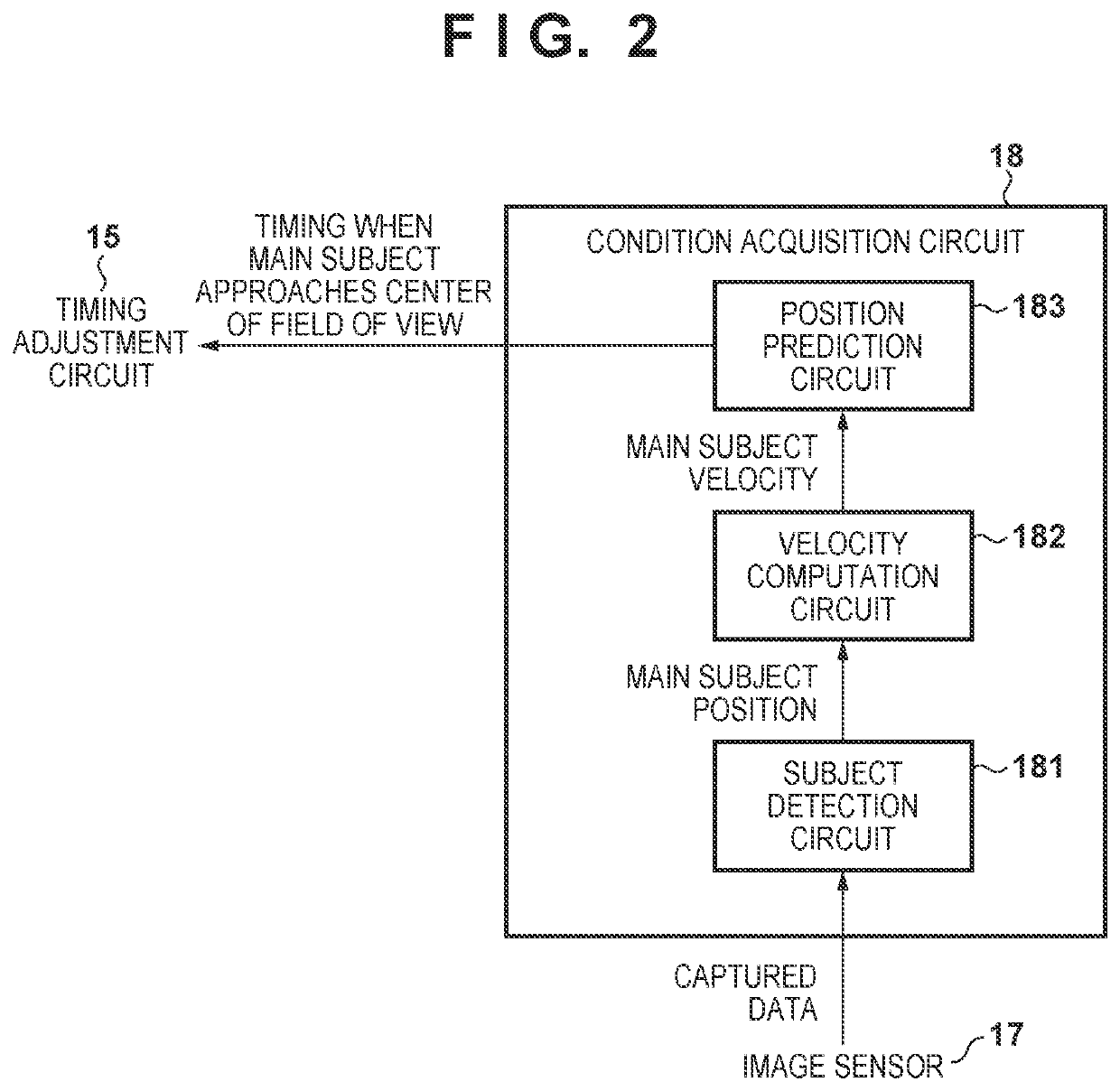
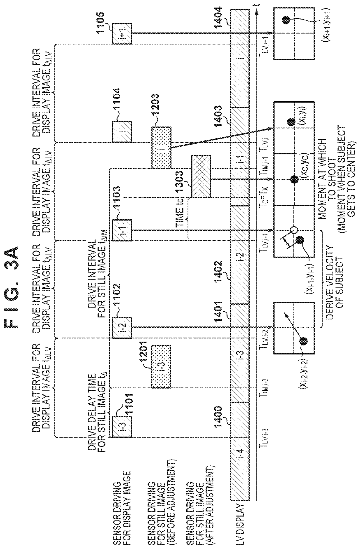
An image capture apparatus comprises an image sensor and an adjustment circuit that adjusts a drive timing of the image sensor. The adjustment circuit, in a case where a second drive time period, which is a drive time period of the image sensor for still image shooting, overlaps with a first drive time period, which is a drive time period of the image sensor for moving image shooting, changes a start timing of the second drive time period to a timing that is based on a movement direction and a movement amount of a main subject.

Description

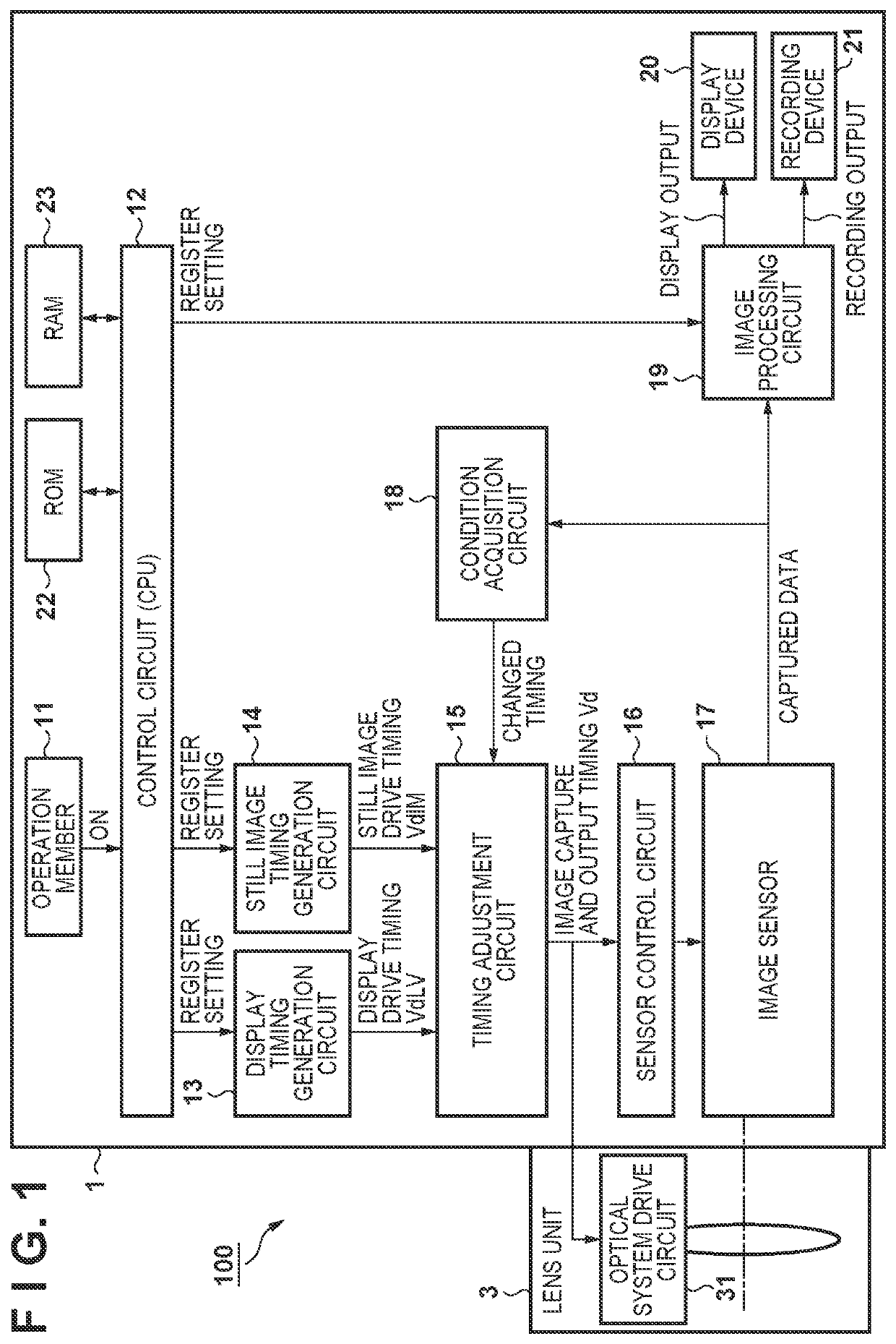
BACKGROUND OF THE INVENTIONField of the Invention[0001]The present invention relates to an image capture apparatus and a control method therefor, and more particularly to an image capture apparatus capable of shooting still images during moving image shooting and a control method therefor.Description of the Related Art[0002]There are digital cameras and electronic devices provided with a camera function (hereinafter, referred to collectively as image capture apparatuses) that have a live view (LV) function. The LV function causes a display device that displays moving images to function as a viewfinder, by executing moving image shooting in parallel with display of the moving images obtained by the moving image shooting. The user is able to adjust the shooting range of moving images and still images for performing recording, using the moving images that are displayed by the LV function.[0003]Generally, since resolution and the like differ between still image data and moving image dat...

Claims


Application Information

Patent Timeline
IPC IPC(8): H04N5/232
CPCH04N5/23293H04N5/23227H04N5/23245H04N23/60H04N23/665H04N23/63H04N23/667
Inventor TANAKA, RYOSUKEEBATA, YUYA
Owner CANON KK
Why Eureka
Try Eureka