Lubrication system and filter placement
a technology of lubrication system and filter, which is applied in the direction of turbines, machines/engines, mechanical equipment, etc., can solve the problems of insufficient service and difficulty in performing filtering system servi
Pending Publication Date: 2020-11-05
VESTAS WIND SYST AS
View PDF1 Cites 0 Cited by
- Summary
- Abstract
- Description
- Claims
- Application Information
AI Technical Summary
Benefits of technology
The patent describes a filtering system for the lubricant in a wind turbine. This system is important because lubricant requires high levels of cleanliness, and it can become contaminated with debris from the moving parts of the components being lubricated. The filtering system can remove this debris and keep the lubricant clean for up to two years. This design results in a wind turbine with lower costs and space requirements.
Problems solved by technology
Furthermore, a fluid used for lubrication needs to be free of any contaminants as these can destroy components that are to be lubricated.
This cannot be done sufficiently when the filter cartridges arranged in upright positions, because performing service on the filtering system will thereby be difficult.
Method used
View moreImage
Smart ImageViewing Examples
Examples
first embodiment
[0035]FIG. 3 illustrates a filtering system according to the invention, the filtering system comprising a cylindrical filter container with filter elements being fluidly connected in series,
second embodiment
[0036]FIG. 4 illustrates a filtering system according to the invention, the filtering system comprising two cylindrical filter containers arranged in parallel, and
[0037]FIG. 5 illustrates a filtering system accommodated in a transport unit.
Login to View More PUM
 Abstract
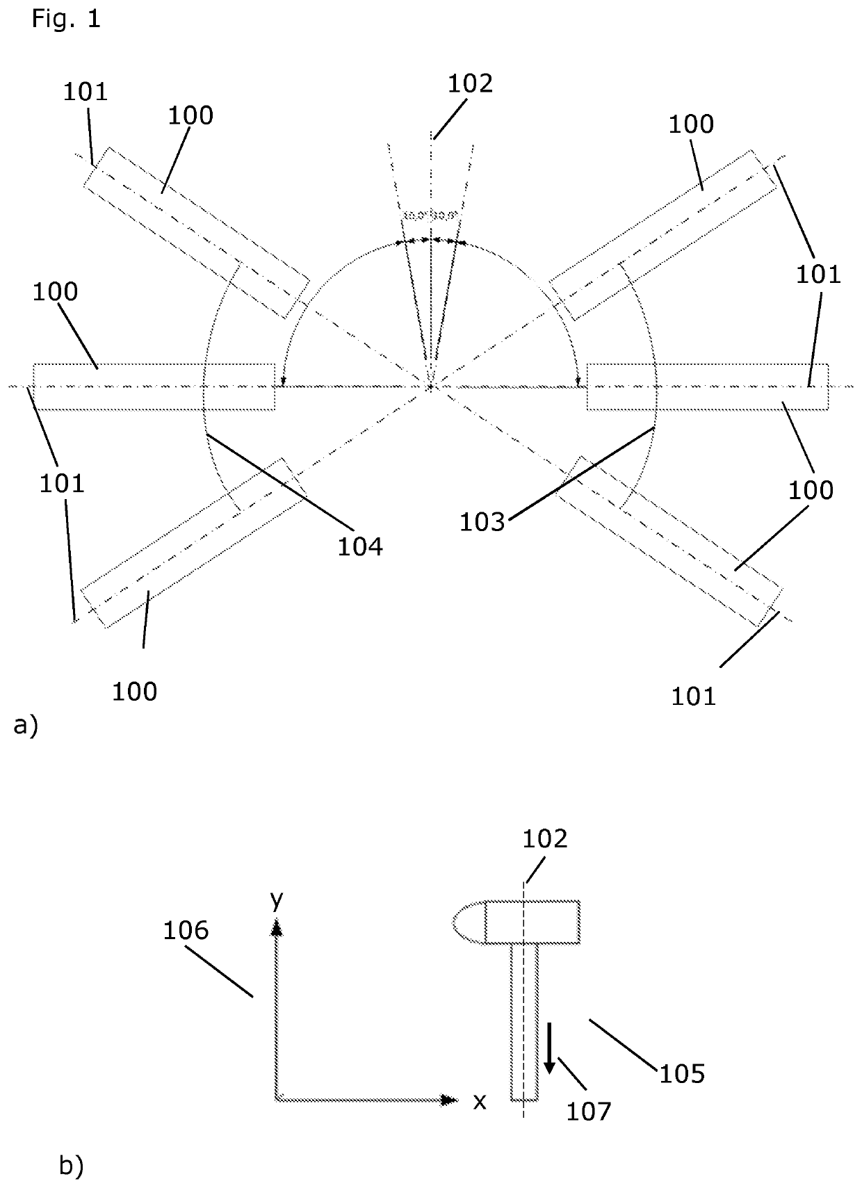
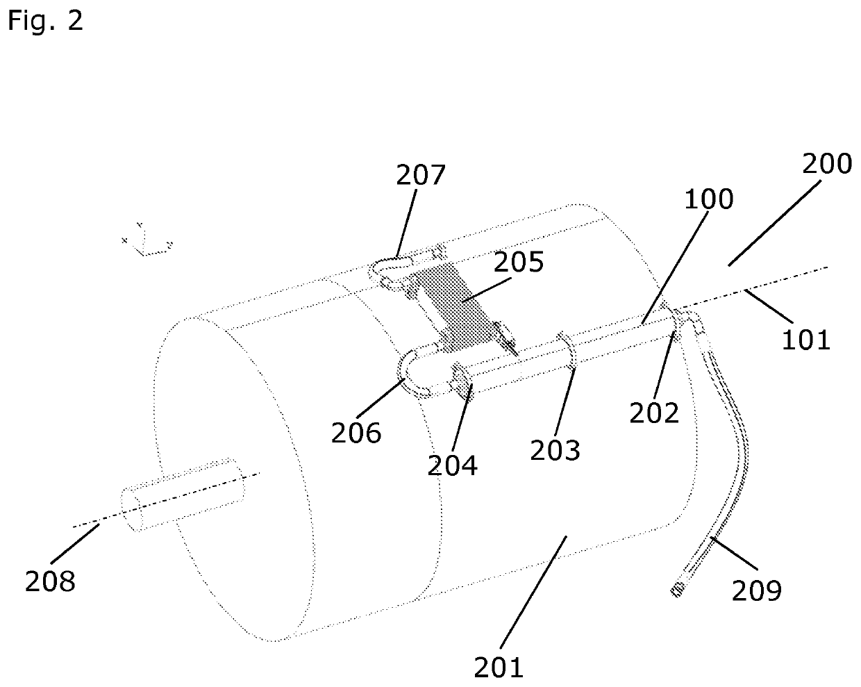
The present invention relates to a lubrication system for a wind turbine (105). The lubrication system comprises at least one or more pumps (310), a tubing system (206, 207, 209), one or more lubricant reservoirs, and a filtering system (200). The filtering system (200) comprises at least one cylindrical filter container (100). Each cylindrical filter container (100, 100a) comprises at least one filter element (301-304). Each cylindrical filter container (100, 100a) defines a central axis (101) along its axial direction and the central axis (101) of each cylindrical filter container (100, 100a) is oriented in a direction forming an angle of at least 10° with respect to a vertical direction (102).
Description
FIELD OF THE INVENTION[0001]The present invention relates to a lubrication system for a wind turbine comprising a filtering system with at least one cylindrical filter container oriented in a direction forming an angle of at least 10° with respect to a vertical direction.BACKGROUND OF THE INVENTION[0002]Wind turbines are currently receiving huge attention as they are considered as an environment friendly and clean alternative energy source. Considerable efforts are made every day to improve wind turbines making them more and more reliable and efficient.[0003]Like any mechanical system, a wind turbine needs proper lubrication to function optimally. Furthermore, a fluid used for lubrication needs to be free of any contaminants as these can destroy components that are to be lubricated. Therefore, a good filtering system within a lubrication system is needed. Normally, filtering systems or filter cartridges are placed in upright positions within ±10° from a vertical direction. However, ...
Claims
Login to View More Application Information
Patent Timeline
 IPC IPC(8): F03D80/70F16N39/06
CPCF16N39/06F16N2210/025F05B2260/98F03D80/70F05B2250/314F05B2260/63Y02E10/72
Inventor NIELSEN, THOMAS KORSGAARD
Owner VESTAS WIND SYST AS
- R&D Engineer
- R&D Manager
- IP Professional
- Industry Leading Data Capabilities
- Powerful AI technology
- Patent DNA Extraction
Learn More Browse by: Latest US Patents, China's latest patents, Technical Efficacy Thesaurus, Application Domain, Technology Topic, Popular Technical Reports.
© 2024 PatSnap. All rights reserved.Legal|Privacy policy|Modern Slavery Act Transparency Statement|Sitemap|About US| Contact US: help@patsnap.com


