Support structure for a frame formwork panel

Active Publication Date: 2020-10-22
PERI SE
View PDF0 Cites 1 Cited by
  • Summary
  • Abstract
  • Description
  • Claims
  • Application Information

AI Technical Summary

Benefits of technology

The technical effect of this patent is to provide an improved support structure.

Problems solved by technology

However, this is complex in the production process, and the support structures of this type cannot be used as universally as those without oblique struts.

Method used


Image

  • Support structure for a frame formwork panel
  • Support structure for a frame formwork panel
  • Support structure for a frame formwork panel

Examples


Embodiment Construction

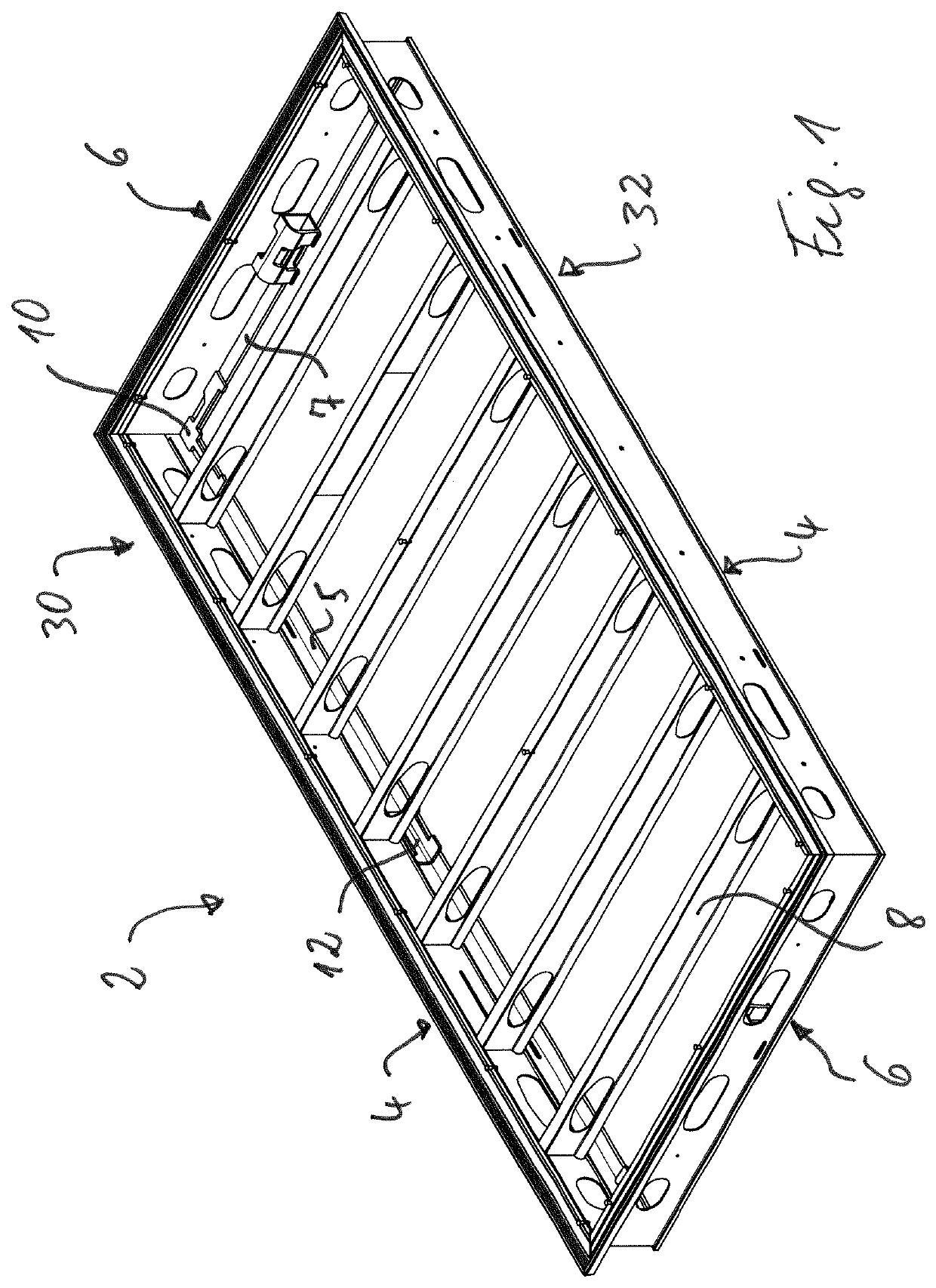
[0043]The support structure 2 shown in FIG. 1 is constructed from two longitudinal edge girders 4, two transverse edge girders 6 and seven transverse intermediate girders 8. The transverse edge girders 6 are positioned perpendicular from the longitudinal edge girders 4. The transverse intermediate girders 8 run parallel to the transverse edge girders 6 and extend from one longitudinal edge girder 4 to the other longitudinal edge girder 4.

[0044]FIG. 1 furthermore shows a corner connecting piece 10 and a positioning piece 12. Three further corner connecting pieces 10 and a further positioning piece 12 are covered by the edge girders 4 and 6.

[0045]It can be seen that the longitudinal edge girders 4 and the transverse edge girders 6 each have, at the rear end, a flange 5 and / or 7 projecting towards the center region of the support structure 2.

[0046]FIG. 2 shows more clearly that the corner connecting piece 10 is a metal piece with two legs 14 running perpendicular to one another. At eac...


PUM

PropertyMeasurementUnit
Angleaaaaaaaaaa

Abstract

A support structure for a frame formwork panel including a support structure and a formwork skin connected to the support structure, the support structure having two longitudinal edge girders and two transverse edge girders, wherein a corner connecting piece which is welded to the two respective edge girders is provided in at least some of the corner regions of the support structure where a longitudinal edge girder and a transverse edge girder come together.

Description

FIELD OF THE INVENTION[0001]The invention relates to a support structure for a frame formwork panel comprising a support structure and a formwork skin connected to the support structure, the support structure having two longitudinal edge girders and two transverse edge girders.BACKGROUND OF THE INVENTION[0002]Support structures with two longitudinal edge girders and two transverse edge girders for frame formwork panels are known in a large number of configurations. In the known support structures, the edge girders mentioned are mostly welded to one another at the four corner regions of the support structure. These welded regions must be able to transmit large forces. Support structures in which oblique struts have been welded in at the corner regions are known as well. However, this is complex in the production process, and the support structures of this type cannot be used as universally as those without oblique struts.SUMMARY OF THE INVENTION[0003]The object of the invention is to...

Claims


Application Information

Patent Timeline
IPC IPC(8): E04G9/06E04G11/50
CPCE04G2009/025E04G11/50E04G9/06B23K5/00B23K5/22B23K37/0443E04G23/0218B28B7/0002E04G2009/028E04G9/02E04G11/48E04G2009/026
Inventor HAEBERLE, WILFRIEDHIEBER, ALEXANDERKIRCHHOFF, STIG
Owner PERI SE
Why Eureka
Try Eureka