
Electronic hydraulic brake device and control method thereof

a technology of electronic brake and control method, which is applied in the direction of braking system, braking components, transportation and packaging, etc., can solve the problems of control device fault, electronic brake device in autonomous vehicles, and serious risk to passengers during driving, so as to improve the braking stability of the vehicle

Active Publication Date: 2020-10-22
HYUNDAI MOBIS CO LTD
View PDF0 Cites 3 Cited by
  • Summary
  • Abstract
  • Description
  • Claims
  • Application Information

AI Technical Summary

Benefits of technology

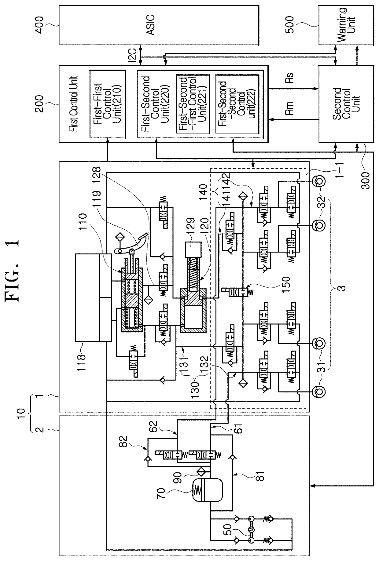
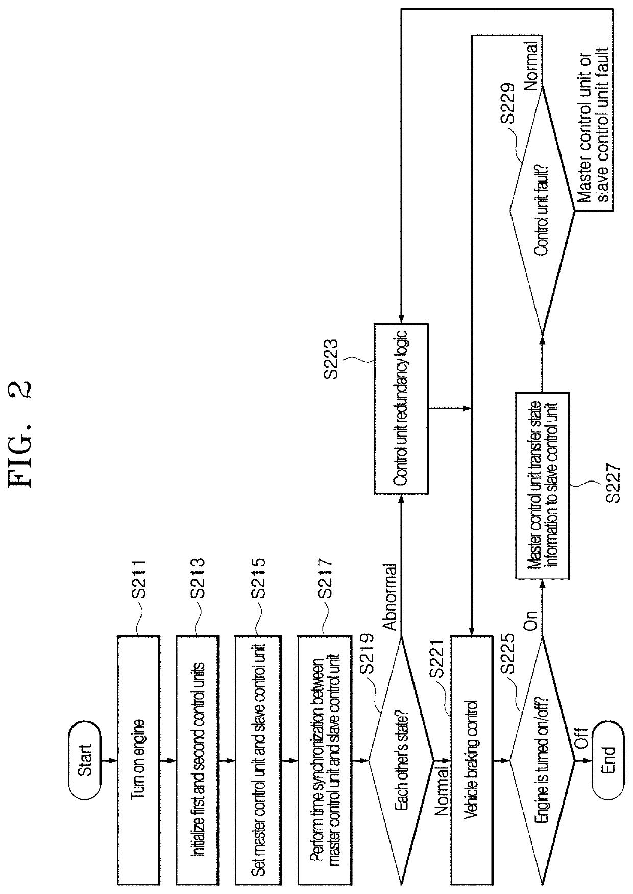
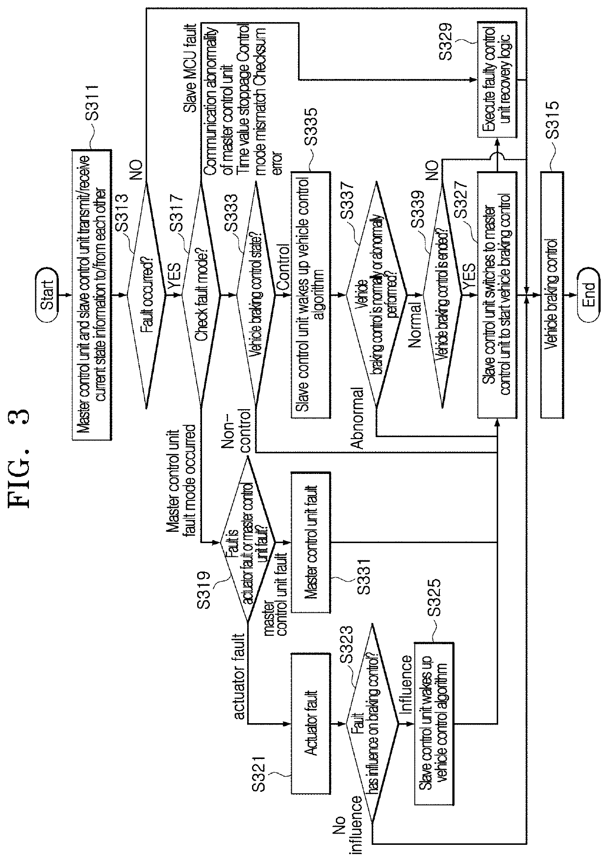
The patent is about an electronic hydraulic brake system that includes a main control unit and a sub control unit. The main control unit monitors the vehicle's brakes and controls them, while the sub control unit takes over in case of a failure or fault in the main control unit. This improves the vehicle's stability and safety during braking. The patent also describes a control method for the brakes that includes pre-determined pressure settings and information on the status of the brakes during startup. Overall, the invention enhances the reliability and safety of electronic brakes in vehicles.

Problems solved by technology

The development trend of electric / hybrid vehicles has been focused on autonomous vehicles, and a fault of an electronic brake device in an autonomous vehicle presents a serious risk to a passenger during driving.
Examples of the fault of the electronic brake device include a hydraulic device fault, a power device fault and a control device fault.
Among the faults, the control device fault has the highest risk level.
That is, when the main MCU is damaged, braking control is stopped, and a driver needs to operate the mechanical brake device to stop the vehicle.
However, since it is difficult to request the driver to pay attention to the vehicle operation state in such a situation that the autonomous vehicles are developed to aim for fully autonomous driving, the backup mechanical brake device may not protect the driver any more.
When a braking command is issued while a vehicle is driven by a driver, the driver may cope with a fault of the main brake device using the backup brake device because the driver steers the vehicle.
However, in the autonomous mode in which a driver's intervention is minimized or a driver does not intervene in operation, the driver cannot cope with a fault of the main brake device or a response time delay inevitably occurs.

Method used


Image

  • Electronic hydraulic brake device and control method thereof
  • Electronic hydraulic brake device and control method thereof
  • Electronic hydraulic brake device and control method thereof

Examples


Embodiment Construction

[0029]The advantages and characteristics of the present disclosure and a method for achieving the advantages and characteristics will be clarified through the following embodiments which will be described in detail with reference to the accompanying drawings. However, it should understood that the present disclosure is not limited to the following embodiments, can be embodied in various different forms, and includes all modifications, equivalents or substitutes which are included in the scope and technical range of the present disclosure. The following embodiments are provided to complete the disclosure of the present disclosure, such that the scope of the present disclosure can be fully understood by those skilled in the art to which the present disclosure pertains. Moreover, detailed descriptions related to publicly known functions or configurations will be ruled out in order not to unnecessarily obscure subject matters of the present disclosure.

[0030]The terms used in this applic...


PUM


Abstract

An electronic hydraulic brake device may include: a brake unit including a main brake unit configured to provide braking hydraulic pressure to a plurality of wheel cylinders through an operation of a motor, and an auxiliary brake unit connected to the main brake unit so as to be filled with high braking hydraulic pressure, and configured to provide braking hydraulic pressure to the plurality of wheel cylinders when an operation error of the main brake unit occurs; a first control unit configured to control the operation of the brake unit, and configured to control the auxiliary brake unit to operate when an operation error of the main brake unit occurs; and a second control unit configured to assist a part of the control of the main brake unit controlled by the first control unit and the control of the auxiliary brake unit.

Description

CROSS-REFERENCE TO RELATED APPLICATION[0001]This application claims priority from and the benefit of Korean Patent Application No. 10-2019-0045336, filed on Apr. 18, 2019, which is hereby incorporated by reference for all purposes as if set forth herein.BACKGROUNDField[0002]Exemplary embodiments of the present disclosure relate to an electronic hydraulic brake device capable of reliably securing the braking stability of a vehicle, and a control method thereof.Discussion of the Background[0003]The development trend of electric / hybrid vehicles has been focused on autonomous vehicles, and a fault of an electronic brake device in an autonomous vehicle presents a serious risk to a passenger during driving. Examples of the fault of the electronic brake device include a hydraulic device fault, a power device fault and a control device fault. Among the faults, the control device fault has the highest risk level.[0004]In the related art, one MCU (Micro Control Unit) uses multiple cores to co...

Claims


Application Information

Patent Timeline
IPC IPC(8): B60T8/17B60T8/40B60T13/62B60Q9/00B60T8/1755
CPCB60T13/62B60T8/17B60Q9/00B60T2270/413B60T8/1755B60T7/12B60T2270/30B60T2270/82B60T2270/404B60T2270/402B60T2260/08B60T8/4081B60T17/22B60T13/745B60T8/885B60T7/042B60T13/662B60T17/221B60T8/172B60T17/04B60R16/023B60T2220/04B60Y2200/91B60Y2200/92
Inventor CHEON, SE YOUNGLIM, JAE ILCHO, BONG GEUNHUR, JAE WOONG
Owner HYUNDAI MOBIS CO LTD
Learn More