
Internal and external clamping method and device of thin-wall tubular part during rotary processing

a technology of internal and external clamping and tubular parts, which is applied in the field of machining technology, can solve the problems of poor clamping effect of tubular parts, no longer applicable clamping methods for filling solid bars, and easy slippage of tubular parts, so as to improve the clamping effect, and improve the effect of clamping

Active Publication Date: 2020-10-22
SOUTH CHINA UNIV OF TECH
View PDF0 Cites 3 Cited by
  • Summary
  • Abstract
  • Description
  • Claims
  • Application Information

AI Technical Summary

Benefits of technology

The present disclosure proposes an effective method and device for internal and external clamping of a thin-wall tubular part during rotary processing. This helps improve the clamping reliability of the thin-wall tubular part and reduces the production cost as compared to traditional methods. The method uses a wedge-shaped sleeve and a clamping cylinder to achieve the external clamping of the tubular part. This can be done by transmitting the forward movement of pull rods to the wedge-shaped sleeve, which causes the clamping cylinder to contract and secure the tubular part. The invention can overcome the problem of poor clamping effect and easy slip during processing.

Problems solved by technology

When the clampable region of the tubular part is short, the tubular part will have a poor clamping effect and is easy to slip during the processing.
However, when the diameter of the mouth portion of the tubular part is smaller than that of the middle portion of the same, this clamping method of filling with the solid bar is no longer applicable.

Method used


Image

  • Internal and external clamping method and device of thin-wall tubular part during rotary processing
  • Internal and external clamping method and device of thin-wall tubular part during rotary processing
  • Internal and external clamping method and device of thin-wall tubular part during rotary processing

Examples


Embodiment Construction

[0034]In order to make the objects, technical solutions and advantages of the present disclosure clearer, the present disclosure will be further described in detail below in combination with specific examples and drawings; however, these embodiments do not limit the scope of protection of the present disclosure.

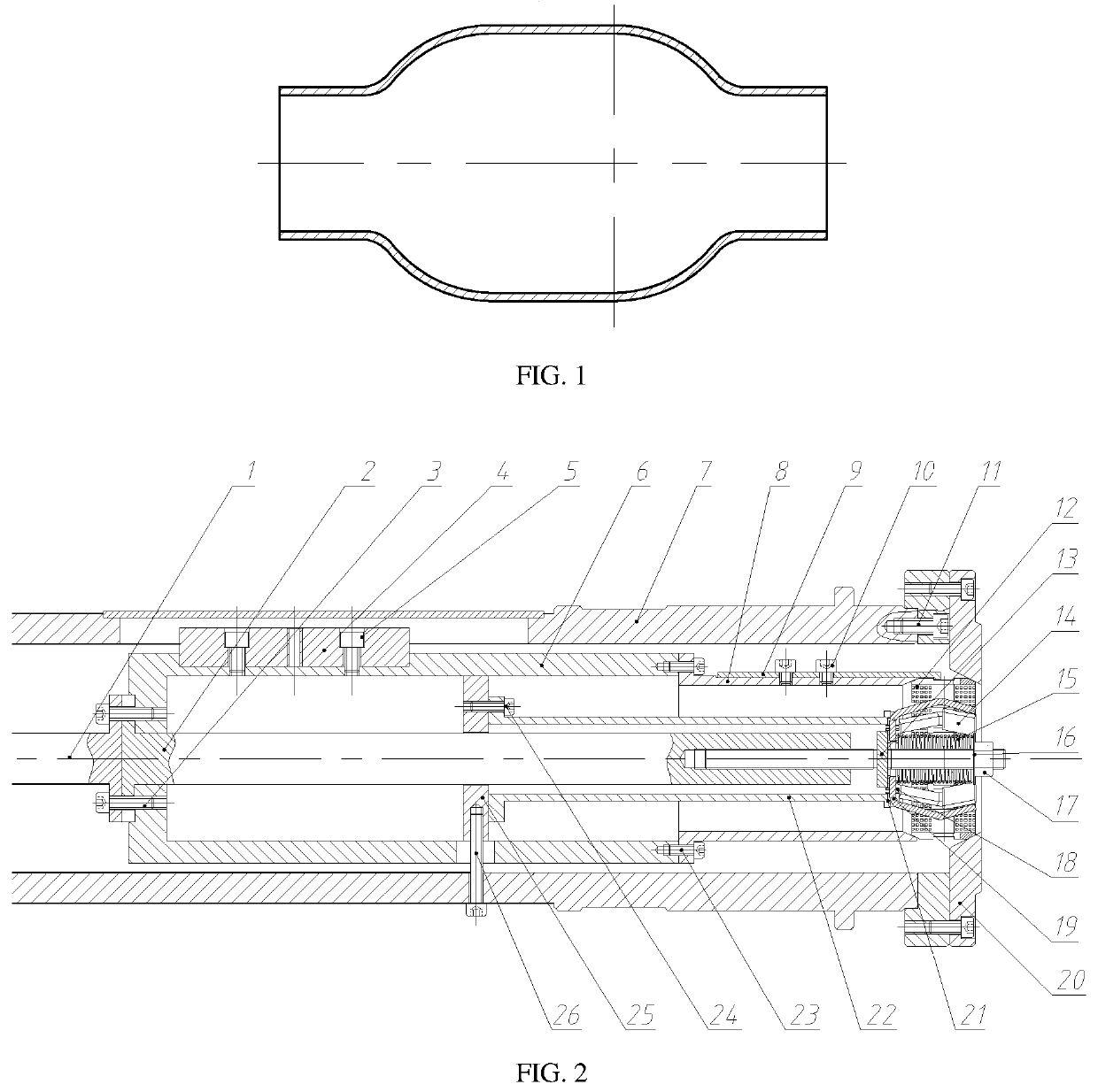
[0035]FIG. 1 is a schematic structural view of a thin-wall tubular part after rotary processing. As shown in FIG. 1, the thin-wall tubular part has a short clampable region, with the diameter of its mouth portion smaller than that of its middle portion.

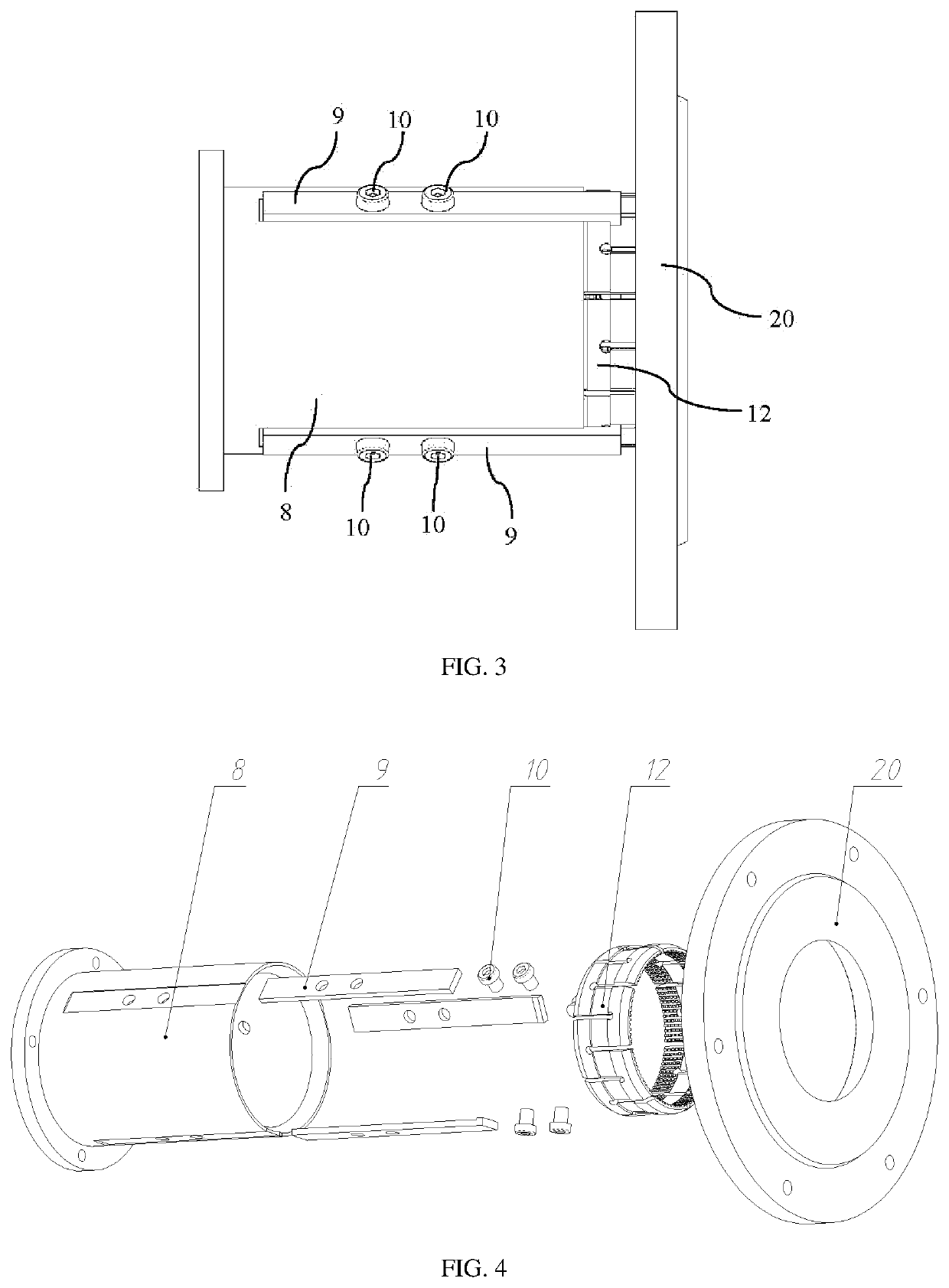
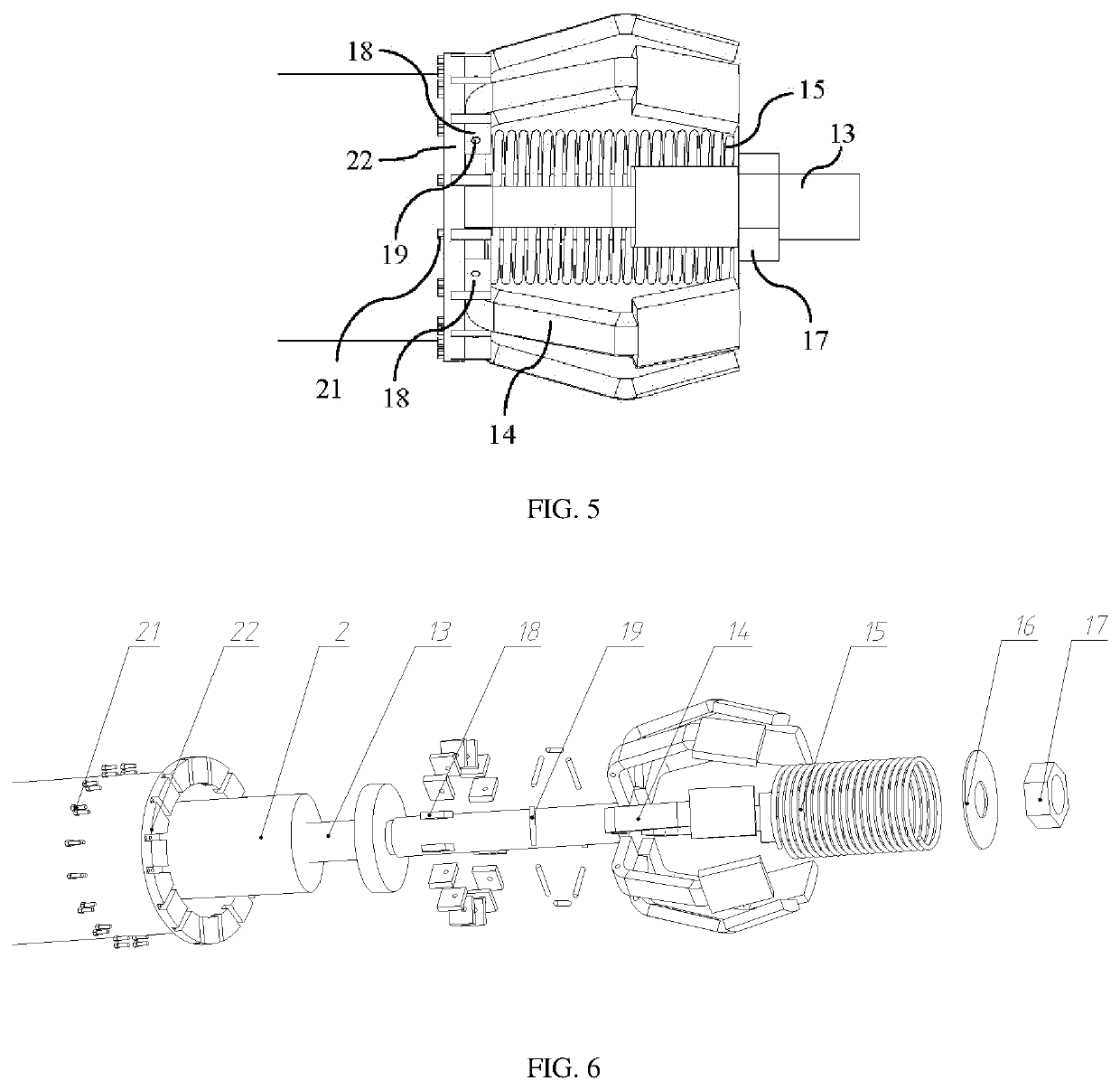
[0036]As shown in FIG. 2, an internal and external clamping device of a thin-wall tubular part during rotary processing comprises a first pull rod 1, a second pull rod 2, an inner cylinder 6, an outer sleeve 7, a wedge-shaped sleeve 8, a hook 9, a clamping cylinder 12, a threaded push rod 13, a support claw ring 14, a spring 15, a washer 16, a nut 17, a support block 18, a rotary shaft 19, a jacket 20, a flange bush 22 and a su...


PUM


Abstract

The present disclosure discloses an internal and external clamping method and device of a thin-wall tubular part during rotary processing. A plurality of support blocks of this device are spaced to form an annular structure around the flange bush; the middle portion of each support block is provided with a through hole; a support claw is provided between every two support blocks, and the side surface of the support claw is provided with the through hole; a rotary shaft penetrates through the through holes in the support claws and the support blocks; the plurality of support claws are spaced to form a support claw ring having the annular structure, and each support claw is formed by connecting the front end, the rear end, and the bottom; the support claw ring is provided in a clamping cylinder, and the thin-wall tubular part is provided between the outside surface of the support claw ring and the inside surface of the clamping cylinder. The clamping cylinder of the present disclosure is contracted under the combined action of a wedge-shaped sleeve and a jacket, and is used for pressing the outer wall of the part, so that the external clamping of the thin-wall tubular part is realized; the support claw ring is turned over and expanded around the rotary shaft between the two support blocks separately, so that the internal clamping of the thin-wall tubular part is realized.

Description

FIELD OF THE DISCLOSURE[0001]The present disclosure invention, belonging to the field of machining technology, relates to clamping of a thin-wall tubular part, in particular to an internal and external clamping method and device of a thin-wall tubular part during rotary processing.BACKGROUND OF THE DISCLOSURE[0002]There is a kind of thin-wall tubular parts in the field of machining. The clamping method of the tubular parts during rotary processing is generally external clamping. When the clampable region of the tubular part is short, the tubular part will have a poor clamping effect and is easy to slip during the processing. Therefore, solid bars are often filled inside the tubular part to achieve internal and external clamping of the tubular part. However, when the diameter of the mouth portion of the tubular part is smaller than that of the middle portion of the same, this clamping method of filling with the solid bar is no longer applicable. Therefore, there is an urgent need for...

Claims


Application Information

Patent Timeline
Patent Type & Authority Applications(United States)
IPC IPC(8): B25B5/14B25B5/04
CPCB25B5/147B25B5/04B23B31/4006B23B31/4026B23B31/42Y02P70/10
Inventor XIA, QINXIANGLONG, JINCHUANCHENG, XIUQUANXIONG, YINGCHAOXIAO, GANGFENG
Owner SOUTH CHINA UNIV OF TECH
Learn More