
Millimeter wave radar modeling-based method for object visibility determination

a technology of object visibility and radar, applied in the direction of reradiation, measurement devices, instruments, etc., can solve the problems of not being able to represent the physical characteristics of millimeter wave radar, and no method using reflection intensity for object visibility determination in sensor models, etc., to achieve the effect of improving the fidelity of the millimeter wave radar model

Active Publication Date: 2020-10-08
JILIN UNIV
View PDF0 Cites 1 Cited by
  • Summary
  • Abstract
  • Description
  • Claims
  • Application Information

AI Technical Summary

Benefits of technology

The patent text describes a method for determining the visibility of objects using millimeter wave radar. The method involves extracting relevant data from the target vehicle's reflection intensity, and then comparing it to a visibility threshold to determine if the object is visible or invisible. The results are then converted and outputted in the required format for the radar model. The technical effect of this method is improved object visibility determination in millimeter wave radar, which can improve safety and efficiency in various applications such as autonomous vehicles.

Problems solved by technology

In virtual sensor models, visibility analysis is usually through geometry culling or ray tracing, which uses only geometric and graphics algorithms, without considering the effects of millimeter-wave propagation and reflection, and thus cannot represent the physical characteristics of the millimeter wave radar.
In addition, no method using reflection intensity has been reported for object visibility determination in a sensor model.

Method used


Image

  • Millimeter wave radar modeling-based method for object visibility determination
  • Millimeter wave radar modeling-based method for object visibility determination
  • Millimeter wave radar modeling-based method for object visibility determination

Examples


embodiments

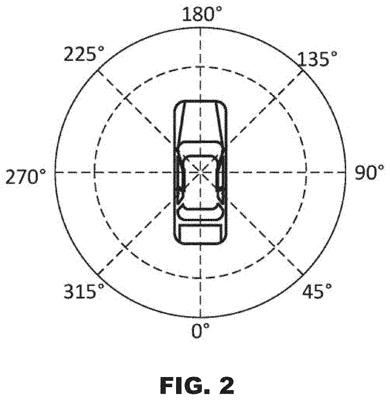
[0056]Prior to target vehicle information detection, a scene module and a vehicle dynamics module in the simulation testing simulator are used to produce a scene culling position and a culling range of a simulation scene according to inputted parameters of a simulated host-vehicle sensor, a mounting position and an angel of the simulated sensor and a shape and a size of the detection area of the simulated sensor, and a motion position of the host vehicle, to perform culling on a traffic participant in the scene, and obtain a corresponding attribute. For example, the traffic participant may be a vehicle. In the description below, the traffic participant is a vehicle (i.e., the target vehicle) by default. It is defined that the target vehicle is at 0 degrees when its head points in the positive direction of the X-axis, as shown in FIG. 2.

[0057]According to an embodiment of the invention, a millimeter wave radar modeling-based method for object visibility determination includes the fol...


PUM


Abstract

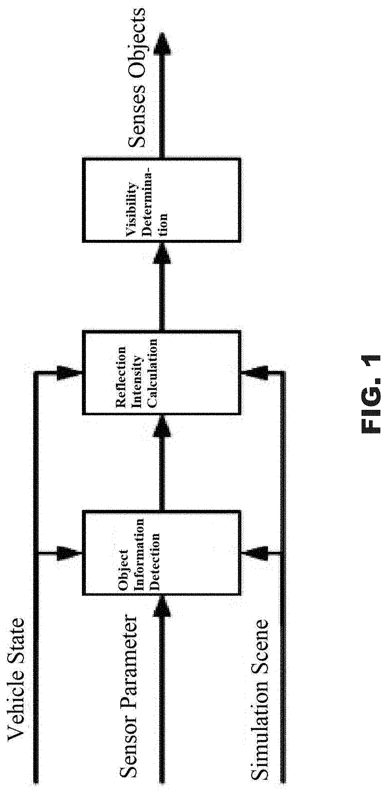
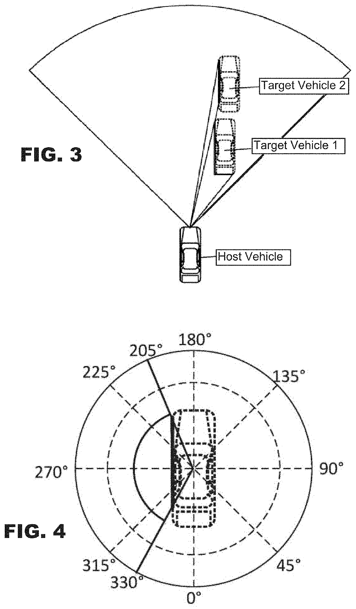
The invention provides a millimeter wave radar modeling-based method for object visibility determination, to solve the problem of object visibility determination based on virtual sensor modeling in intelligent vehicle simulation and testing, and improve the fidelity of sensor modeling while meeting simulation efficiency requirements. It includes the steps of target vehicle information detection to obtain target vehicle information; target vehicle reflection intensity simulation: for each target vehicle performing geometry culling on the target vehicle, discarding completely-invisible target vehicles, and calculating visible section information for each target vehicle that has a visible section, and reflection intensity calculation; target vehicle visibility determination: analyzing visibility of the target vehicle according to the target vehicle reflection intensity, and converting and outputting information of a visible object into an expression form of a real millimeter-wave radar sensing an object.

Description

CROSS-REFERENCE TO RELATED APPLICATIONS AND CLAIM TO PRIORITY[0001]This application is related to Patent Application No. 201910270687.3 filed Apr. 4, 2019 in China, the disclosure of which is incorporated herein by reference and to which priority is claimed.FIELD OF THE INVENTION[0002]The invention relates to intelligent vehicle testing and validation, and in particular to a millimeter wave radar modeling-based method for object visibility determination.BACKGROUND AND SUMMARY OF THE INVENTION[0003]Virtual testing is widely recognized as the most effective way to intelligent vehicle development. Virtual sensor modeling is one of the most important elements of the virtual testing of intelligent vehicles; the fidelity of the virtual sensor model determines how much a virtual testing can replace a real testing. In virtual sensor models, visibility analysis is usually through geometry culling or ray tracing, which uses only geometric and graphics algorithms, without considering the effec...

Claims


Application Information

Patent Timeline
Patent Type & Authority Applications(United States)
IPC IPC(8): G01S13/931G01S7/40G01S13/52
CPCG01S13/52G01S7/40G01S13/931G01S7/4052
Inventor ZHAN, JUNDONG, XUECAIDUAN, CHUNGUANGWANG, ZHANGULIU, RONGYANG, KAIZHU, HUAINAN
Owner JILIN UNIV
Learn More