
Process and system for producing synthesis gas

a technology of synthesis gas and process, applied in the direction of combustible gas chemical modification, combustible gas purification/modification, chemical/physical/physico-chemical processes, etc., can solve the problem of outweighing the potential disadvantage of a minor increase in the amount of methane in the synthesis gas stream

Active Publication Date: 2020-10-08
HALDOR TOPSOE AS
View PDF0 Cites 1 Cited by
  • Summary
  • Abstract
  • Description
  • Claims
  • Application Information

AI Technical Summary

Benefits of technology

This patent describes a method of producing synthesis gas using an adiabatic post converter with a second catalyst. The second catalyst is designed to improve the production of methanation and reverse water gas shift reactions. The heated CO2 rich gas stream is combined with the first synthesis gas stream and the second catalyst is used to catalyze the steam methane reforming, methanation, and reverse water gas shift reactions. This method has the advantage of producing a synthesis gas with a high concentration of carbon monoxide and alleviating the risk of carbon formation on the catalyst. The temperature of the heated CO2 rich gas stream should be between 500°C and 1,110°C to avoid carbon formation. The hydrocarbon gas may also undergo adiabatic prereforming to convert higher hydrocarbons and remove the risk of carbon formation in subsequent process steps. The second catalyst can be a steam reforming catalyst or a methanation catalyst, such as Ni / MgAl2O4, Ni / Al2O3, or Ni / CaAl2O4. Overall, this method allows for efficient production of synthesis gas with a high concentration of carbon monoxide.

Problems solved by technology

However, the advantage of providing a synthesis gas with a high concentration of carbon monoxide whilst alleviating the risk of carbon formation on the catalyst within the adiabatic post converter outweighs the potential disadvantage of a minor increase in the amount of methane in the synthesis gas stream.

Method used


Image

  • Process and system for producing synthesis gas
  • Process and system for producing synthesis gas
  • Process and system for producing synthesis gas

Examples


example

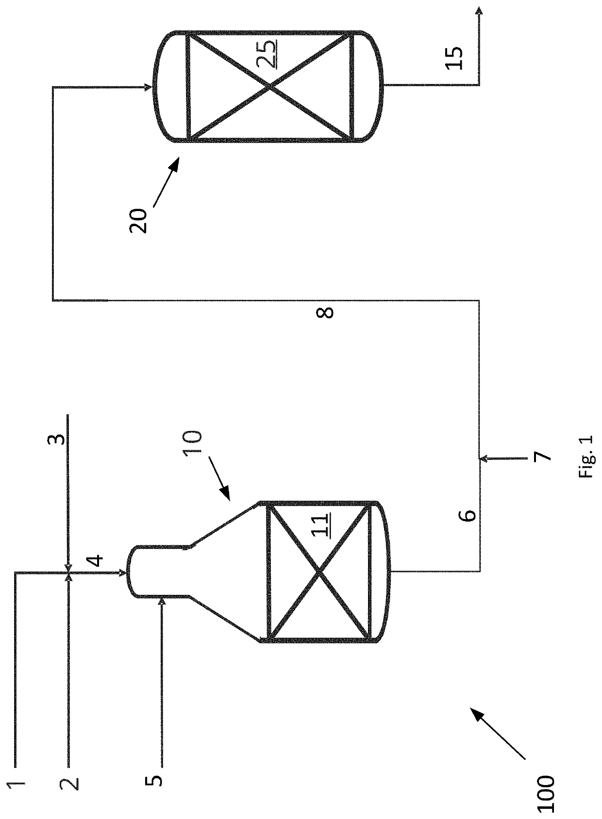
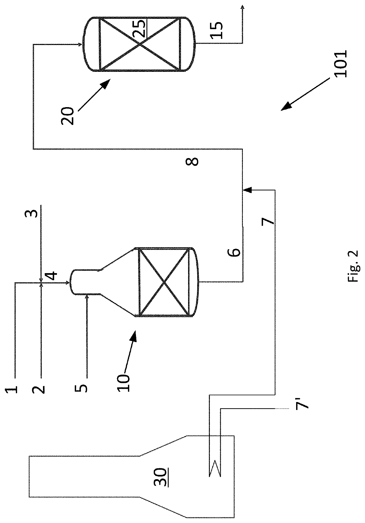
[0060]An example calculation of the process is given in Table 1 below. A hydrocarbon feed stream 4 comprising a hydrocarbon gas 1, a CO2 rich gas stream 2 and steam 3 and having a S / C ratio of 0.6 is fed to the ATR reactor 10 of the invention as shown in FIG. 1. The hydrocarbon feed stream 4 is heated to 650° C. prior to being let into the ATR reactor 10. The ATR reactor 10 produces a first synthesis gas stream 6. An oxygen containing stream 5 is added to the ATR reactor and the amount thereof is adjusted such that the temperature of the first synthesis gas stream 6 is 1050° C.

[0061]The total flow of all components in all inlet streams to the ATR reactor and the flow of all components in the first synthesis gas stream 6 are given in the column headed “ATR 10” in Table 1.

[0062]A CO2 rich gas stream is heated to a heated CO2 rich gas stream having a temperature of 650° C. and the combined gas (the first synthesis gas stream and the heated CO2 gas rich stream) enters the adiabatic post...


PUM

PropertyMeasurementUnit
temperatureaaaaaaaaaa

Abstract

A process for producing synthesis gas, the process including the steps of: a) in a reforming reactor, reacting a hydrocarbon feed stream together with an oxidant gas stream, thereby producing a first synthesis gas stream; b) providing a heated CO2 rich gas stream to an adiabatic post converter including a second catalyst active for catalyzing steam methane reforming, methanation and reverse water gas shift reactions; and c) in the adiabatic reforming post converter, letting at least a part of the first synthesis gas stream and the heated CO2 rich gas stream undergo steam methane reforming, methanation and reverse water gas shift reactions to thereby provide a product gas stream, the product gas stream being a synthesis gas stream. Also, a system for producing synthesis gas.

Description

FIELD OF THE INVENTION[0001]Embodiments of the invention generally relate to a system and a process for producing synthesis gas. In particular, the invention relates to a system and a process aimed at producing a reformed stream with a relatively low H2 / CO ratio.BACKGROUND[0002]Catalytic synthesis gas production by steam reforming of a hydrocarbon feed has been known for decades. The endothermic steam reforming reaction is typically carried out in a steam methane reformer (SMR). A steam reformer or steam methane reformer has a number of catalyst filled tubes placed in a furnace or fired heater to provide the heat for the endothermic reaction. The tubes are normally 10-14 meters in length and 7-15 cm in inner diameter. The heat for the endothermic reaction is supplied by combustion of fuels in burners in the furnace. The synthesis gas exit temperature from the steam reformer depends on the application of the synthesis gas but will normally be in the range from 650° C.-980° C.[0003]It...

Claims


Application Information

Patent Timeline
Patent Type & Authority Applications(United States)
IPC IPC(8): C01B3/38B01J19/24B01J19/00
CPCC01B3/386C01B3/388B01J2219/0004C01B2203/085C01B2203/0233B01J19/245C01B2203/0244C01B3/382B01J19/0013C01B2203/0261C01B2203/1241B01J2219/00157C01B2203/0811B01J2219/00135C01B3/384C01B2203/0283C10K3/026
Inventor MORTENSEN, PETER MØLGAARDAASBERG-PETERSEN, KIM
Owner HALDOR TOPSOE AS
Learn More