Cleaning unit, cartridge, image forming apparatus
a technology of image forming apparatus and cleaning blade, which is applied in the direction of electrographic process apparatus, optics, instruments, etc., can solve the problems of insufficient waste toner amount needed to secure lubricity between the cleaning blade and the photosensitive drum, and the cleaning blade may be tucked up, so as to achieve high waste toner transport ability and increase the effect of transport ability
- Summary
- Abstract
- Description
- Claims
- Application Information
AI Technical Summary
Benefits of technology
Problems solved by technology
Method used
Image

Examples
embodiment 1
Overall Description of Image Forming Apparatus
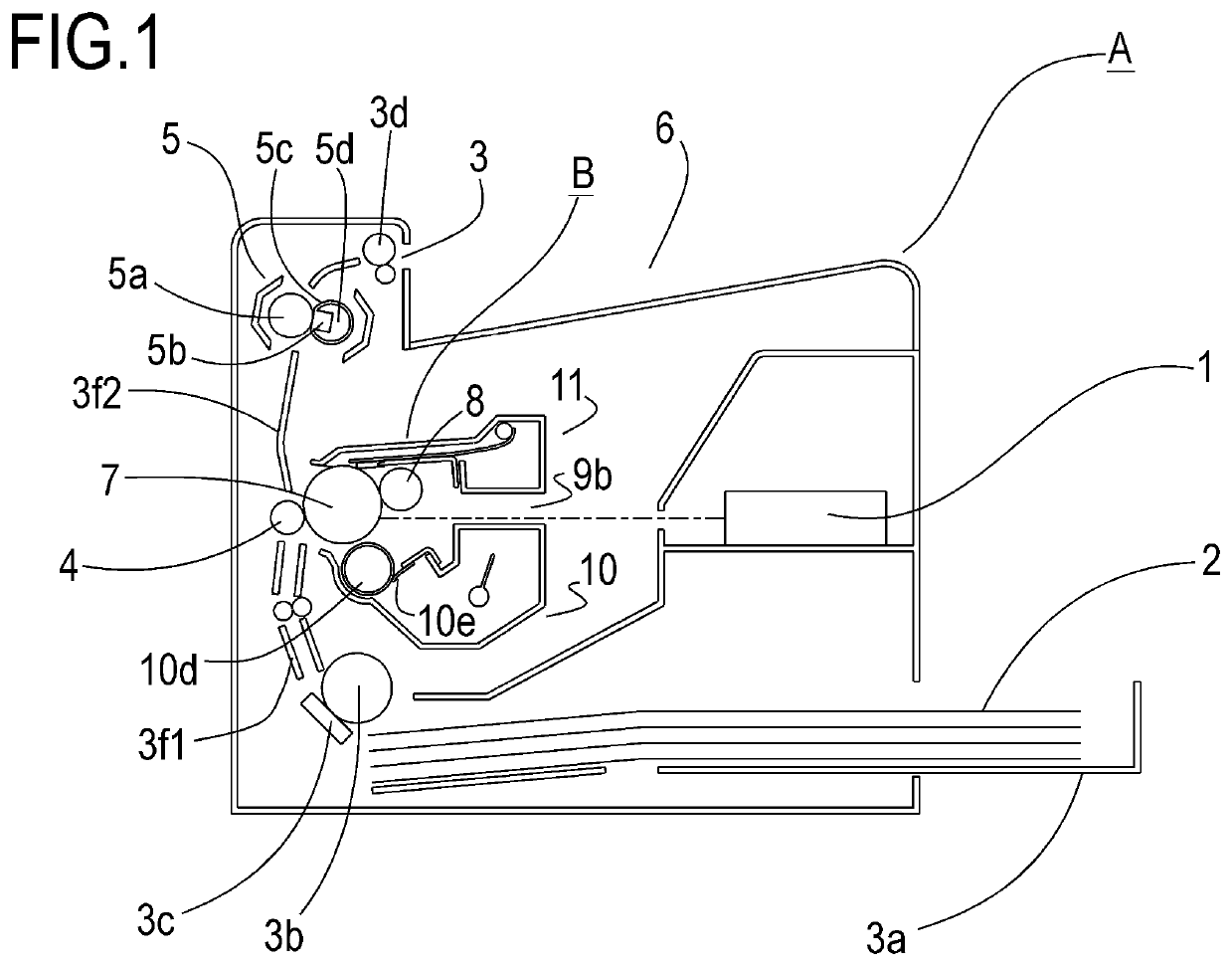
[0056]The overall structure of an electrophotographic image forming apparatus (hereafter image forming apparatus) will be explained next with reference to FIG. 1. FIG. 1 is a schematic cross-sectional diagram of an image forming apparatus fitted with a cartridge B according to Embodiment 1 of the present invention. More specifically, FIG. 1 is a schematic cross-sectional diagram of a laser beam printer which is one implementation of an image forming apparatus.
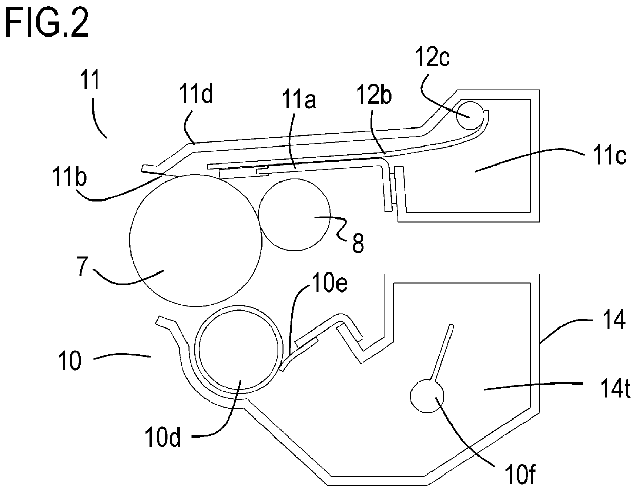
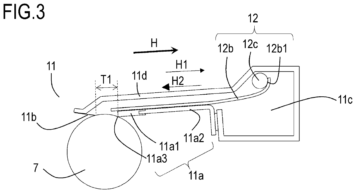
[0057]The attitudes of the image forming apparatus, process cartridge and cleaning unit 11 illustrated in FIG. 1 to FIG. 3 are attitudes at the time of use of the image forming apparatus. The positional relationships, directions and so forth of the various members in the present specification denote positional relationships, directions and so forth in these attitudes. Specifically, a top-bottom direction on the paper in FIG. 1 to FIG. 3 corresponds to a vertical direction, and a lef...
embodiment 2
[0093]A second example of the present invention will be explained next.
[0094]In Embodiment 1, a relationship between the longitudinal widths of the cleaning blade 11a and the waste toner transport member 12b was explained. In the present Embodiment 2 a relationship is explained that includes also the longitudinal width of a toner coat region 10R on the developing roller 10d, in addition to the above longitudinal widths. The configuration of the main body A and of the cartridge B, as well as the material, thickness, driving condition and so forth of the waste toner transport member 12b, are identical to those in Embodiment 1, and will be omitted herein.
[0095]Longitudinal Positional Relationship Between Cleaning Blade 11a, Waste Toner Transport Member 12b and Toner Coat Region 10R
[0096]A relationship between the widths (longitudinal widths) of the cleaning blade 11a, the waste toner transport member 12b and the toner coat region 10R in the longitudinal direction will be explained next...
embodiment 3
[0102]A third example of the present invention will be explained next.
[0103]In the present Embodiment 3, a configuration will be explained in which the transport amount of waste toner differs between the longitudinal-direction ends of the waste toner transport member 12b and portions other than the longitudinal-direction ends. Specifically, the configuration of Embodiment 3 provides adjustment portion for adjusting the transport amount of toner by the waste toner transport member 12b in such a manner that the ends (end region) of the waste toner transport member 12b in the longitudinal direction are smaller than in a region (in particular, a central region) excluding those ends.
[0104]Features not particularly described in Embodiment 3 are identical to those in the examples above, and will not be explained again herein.
[0105]As illustrated in FIG. 8A and FIG. 8B, in the configuration of the present Embodiment 3 the shape of the upstream end of the waste toner transport member 12b is ...
PUM
 Abstract
Description
Claims
Application Information
 - R&D
- Intellectual Property
- Life Sciences
- Materials
- Tech Scout
- Unparalleled Data Quality
- Higher Quality Content
- 60% Fewer Hallucinations
Browse by: Latest US Patents, China's latest patents, Technical Efficacy Thesaurus, Application Domain, Technology Topic, Popular Technical Reports.
© 2025 PatSnap. All rights reserved.Legal|Privacy policy|Modern Slavery Act Transparency Statement|Sitemap|About US| Contact US: help@patsnap.com