Droplet discharge apparatus

a technology of droplet and discharge tube, which is applied in the field of droplet discharge tube, can solve the problems of large size of the tank, waste of prepared ink, and inability to achieve desired color by such adjusting, and achieve the effect of reducing the liquid flow ra

Active Publication Date: 2020-10-01
SEIKO EPSON CORP
View PDF0 Cites 1 Cited by
  • Summary
  • Abstract
  • Description
  • Claims
  • Application Information

AI Technical Summary

Benefits of technology

[0044]may reduce a liquid flow rate of the first flow path system by controlling the fifth valve when transferring the cleaning liquid stored in the cleaning liquid container to the first ink container through the cleaning liquid flow path and the common flow path system.

Problems solved by technology

However, a desired color may not be obtained by such adjusting.
Further, when the amount of ink to be used is large as in a printing field, the size of the tank needs to be large, and waste often occurs in the prepared ink when replacing the ink.

Method used


Image

  • Droplet discharge apparatus
  • Droplet discharge apparatus
  • Droplet discharge apparatus

Examples


Embodiment Construction

[0082]Hereinafter, an embodiment of the present disclosure will be described. The embodiment described below describes an example of the present disclosure. The present disclosure is not limited at all by the embodiment described below. The present disclosure includes various modified examples implemented within the scope not changing the gist of the present disclosure. All of the configurations described below are not necessarily essential components of the present disclosure.

[0083]1. Configuration of Droplet Discharge Apparatus

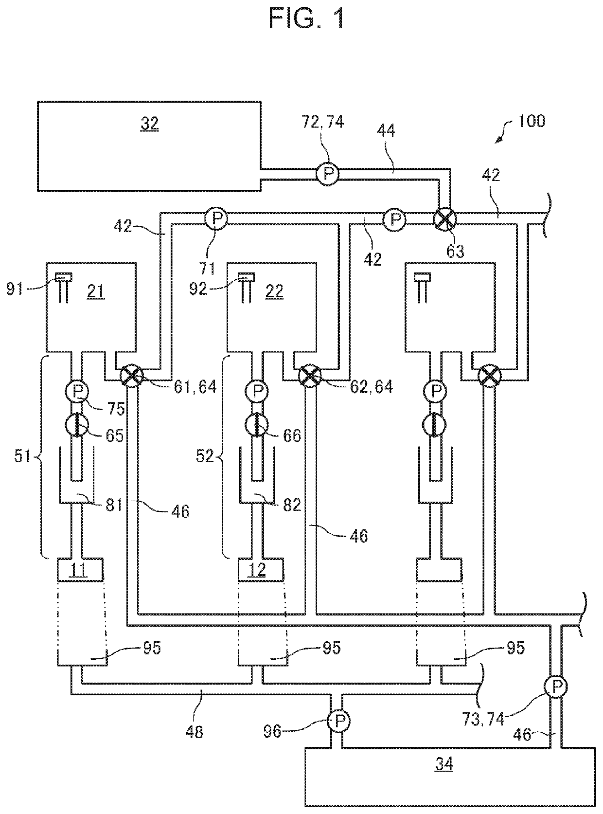
[0084]FIG. 1 is a schematic diagram of a main part of a droplet discharge apparatus 100 according to the embodiment. The droplet discharge apparatus 100 includes a first head 11, a first ink container 21 that stores first ink to be supplied to the first head 11, a second head 12, a second ink container 22 that stores second ink to be supplied to the second head 12, a cleaning liquid container 32 that stores cleaning liquid, a common flow path system 42 that ...


PUM


Abstract

A droplet-discharge-apparatus includes a first-head, a first-ink-container storing first-ink, a second-head, a second-ink-container storing second-ink, a cleaning-liquid-container storing cleaning-liquid, a common-flow-path-system, a cleaning-liquid-flow-path, a first-pomp feeding the first-ink from the first-ink-container to the second-ink-container through the common-flow-path-system, a second-pomp feeding the cleaning-liquid from the cleaning-liquid-container to the first-ink-container through the cleaning-liquid-flow-path and the common-flow-path-system, a first-valve controlling a liquid flow rate between the common-flow-path-system and the first-ink-container, a second-valve controlling a liquid flow rate between the common-flow-path-system and the second-ink-container, a third-valve controlling a liquid flow rate between the common-flow-path-system and the cleaning-liquid-flow-path, and a control-unit. The control-unit transfers the first-ink from the first-ink-container to the second-ink-container by controlling the first-valve, the second-valve, the third-valve, and the first-pomp, and transfers the cleaning-liquid from the cleaning-liquid-container to the first-ink-container by controlling the first-valve, the second-valve, the third-valve, and the second-pomp.

Description

[0001]The present application is based on, and claims priority from JP Application Serial Number 2019-061301, filed Mar. 27, 2019, the disclosure of which is hereby incorporated by reference herein in its entirety.BACKGROUND1. Technical Field[0002]The present disclosure relates to a droplet discharge apparatus.2. Related Art[0003]The droplet discharge apparatus is an apparatus that discharges liquid droplets from fine nozzles and attaches the liquid droplets to a recording medium. The droplet discharge apparatus has a characteristic to be able to quickly record a high-resolution and high-quality image. In an ink jet recording method using the droplet discharge apparatus, an image is formed by discharging inks of a plurality of colors.[0004]The droplet discharge apparatus is also used for textile printing. The textile printing may be performed by, for example, using an ink set of colors including cyan (C), magenta (M), yellow (Y), black (BK), and the like, and mixing colors and adjus...

Claims


Application Information

Patent Timeline
Patent Type & Authority Applications(United States)
IPC IPC(8): B41J2/175
CPCB41J2/17566B41J2/17596B41J2/175B41J2/1707B41J2/16552B41J2/16508B41J2/16523
Inventor OZAWA, KINYAYOKOYAMA, TAKAYUKI
Owner SEIKO EPSON CORP
Why Eureka
Try Eureka