
Control method and system for filtering power line interferences

a power line interference and control method technology, applied in the field of signal filtering, can solve the problems of affecting the analysis of ecg signals, affecting the accuracy of ecg signals, etc., and achieve the effect of high fidelity and accuracy, and clean signals

Active Publication Date: 2020-09-24
MAISONBURG SHENZHEN TECH DEV CO LTD
View PDF0 Cites 2 Cited by
  • Summary
  • Abstract
  • Description
  • Claims
  • Application Information

AI Technical Summary

Benefits of technology

The invention is about a control method and system for filtering out power line interference from electrocardiogram (ECG) signals. The technical problem addressed by the invention is the distortion and loss of signals caused by conventional notch filters used to remove power line interference. The current filtering technologies suffer from various issues related to either loss or distortion of signals, which is especially critical in high frequency ECG analysis. The invention proposes a new method to solve this problem and provide a cleaner signal for accurate ECG analysis.

Problems solved by technology

However, measurements of human ECGs in hospitals are often contaminated by power line interferences.
The complex electrical environment in which these measurements are made makes these kinds of interferences ubiquitous.
Consequently, power line interferences are important noise sources that often hinder the analysis of ECG signals.
However, if there is a non-stationary electromagnetic impact in the measurement environment, the embedded linear filter in ECG machines cannot reliably remove power line inferences.
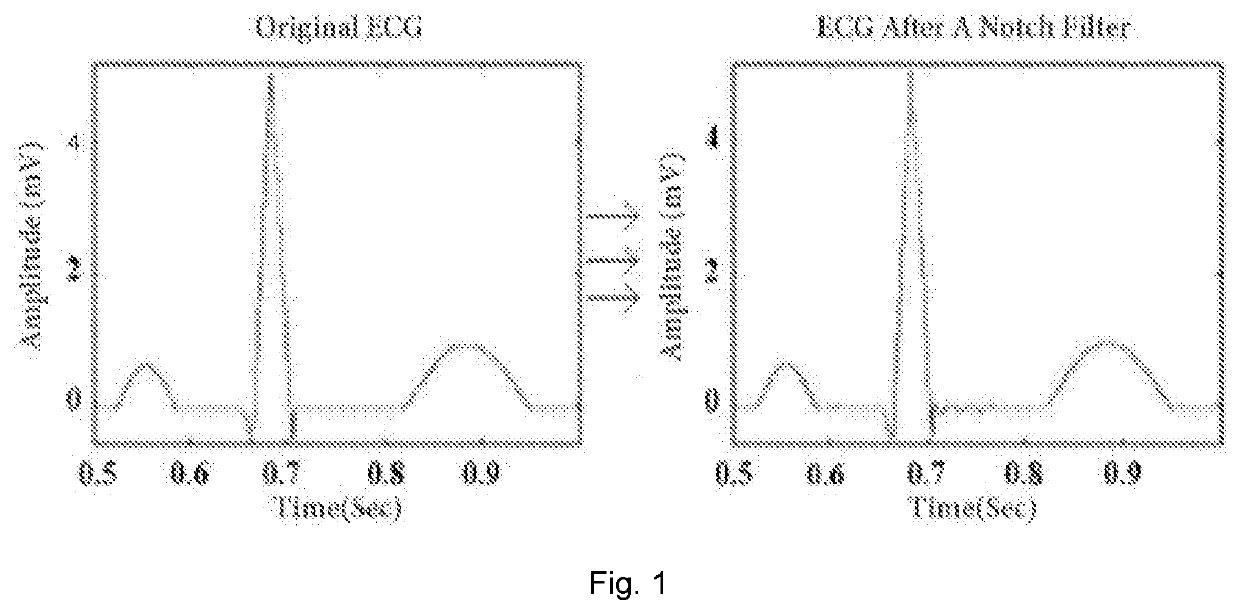
For instance, a notch filter by means of a narrow band stop filter often causes ringing right after a large pulse, which presents an additional interference to the signal.
This ringing complicates the observation of the real information in the signal.
However, the wider the stop frequency band used, the greater the number of signals prone to loss besides power line frequency interferences.
These limitations negatively affect many otherwise useful applications; for example, the VLPs reflecting myocardial infarction happen to fall into the ST segment at the end of a QRS complex and their amplitude is only 3-25 micro volts (uV), while their frequency ranges from 40 Hz through 500 Hz.
Therefore, the use of notch filter techniques implemented by either hardware or software is not allowed by major heart associations worldwide in their published measurement standards.
Due to this ban, VLP measurements in clinical applications suffer from much interference.
Adaptive filtering techniques may solve the ringing response following a sudden amplitude change such as with the QRS complex, but they still suffer from finite response times and are not always satisfactory in VLP detection.
Such problems are inherent to the technology and difficult to correct.
Although this method is very helpful in solving the ringing problem caused by conventional notch filters, there are two potential issues.
First, there is a bandwidth dilemma when applying the band pass filter to extract the power line interference in the linear region.
Setting the bandwidth wider would cause the loss of signals in spite of favoring the power line frequency change, whereas setting the bandwidth too narrow could lead to missing the power line interference entirely since the power line frequency may change over the preset range.
Second, if removing higher order harmonics is required, a comb filter has to be implemented, which further complicates the system and leads to more signal loss in the vicinities of the higher order harmonic frequencies.
In summary, the current filtering technologies suffer from various issues related to either loss or distortion of signals as mentioned above when removing power line interferences.

Method used


Image

  • Control method and system for filtering power line interferences
  • Control method and system for filtering power line interferences
  • Control method and system for filtering power line interferences

Examples


Embodiment Construction

[0027]In order to elucidate the technical approach of and the problems solved by the invention, the present invention will be further described in detail below with reference to the accompanying drawings and embodiments. It is understood that the specific embodiments described herein are merely illustrative of the invention and are not intended to limit the invention.

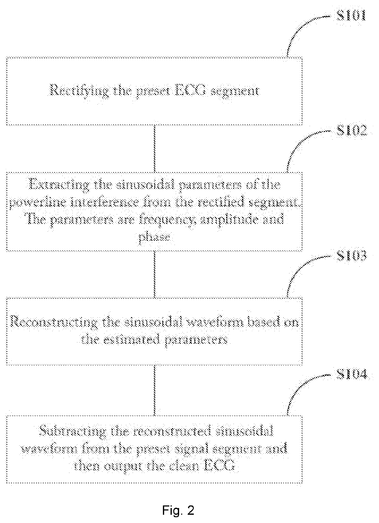
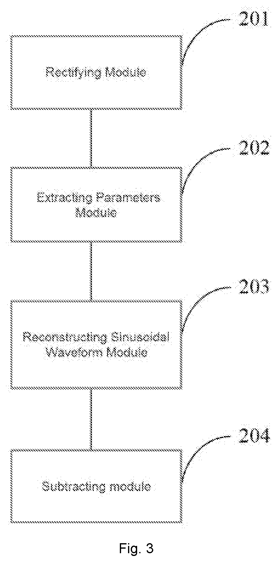
[0028]The solution provides a control method and a control system for filtering the power frequency interference signal, wherein the control method comprises the following: First, each channel of the multi-channel ECG signal is segmented around the QRS wave, and the segmented signal is rectified. This nonlinear processing doubles the frequency of the original power frequency interference signal, for example, from 50 Hz to 100 Hz, thereby improving the accuracy of detecting the interference frequency. The frequency, amplitude, and phase of the power frequency interference signal in the ECG recordings of each channel of t...


PUM


Abstract

A control method and system for filtering power line interference is disclosed. The control method includes the following steps. First, ECG signals are pre-segmented and rectified; then the sinusoidal frequency, amplitude, and phase of the rectified segmented signals are extracted. These estimated sinusoidal parameters from each recorded channel are weighted by their individual signal to noise ratios before being averaged to achieve the optimal powerline frequency, amplitude, and phase. Based on these optimal sinusoidal parameters, the individual sinusoidal waveform is reconstructed and then is subtracted from the corresponding ECG segment, in order to obtain the clean ECG signals. This method of filtering the powerline interference through removal from recorded signals enables accurate measurement without any ringing effect that could lead to signal distortion issues. Thus this invention solves the ringing problem encountered by traditional notch filter techniques when signal amplitude suddenly changes in a measurement.

Description

TECHNICAL FIELD[0001]The invention belongs to the technical field of signal filtering; in particular, it relates to a control method and a control system for filtering out power line interference from electrocardiogram (ECG) signals.PRIOR ART[0002]Electrocardiography (ECG) is widely used as a vital physiological index in clinical applications. However, measurements of human ECGs in hospitals are often contaminated by power line interferences. The complex electrical environment in which these measurements are made makes these kinds of interferences ubiquitous. Such power line interferences can be characterized as sinusoidal waveforms with 50 / 60 Hz fundamental frequencies and higher harmonics, wherein the 50 Hz fundamental frequency dominates in Asia and Europe while 60 Hz dominates in northern American power supply systems. The frequency band of the conventional ECG ranges from 0.05 up to 100 Hz, the high-frequency QRS analysis ranges from 80 to 300 Hz, and while the frequency band o...

Claims


Application Information

Patent Timeline
Patent Type & Authority Applications(United States)
IPC IPC(8): A61B5/04A61B5/0402A61B5/00G01R13/00G01R29/26A61B5/308
CPCG01R13/00A61B5/7217A61B5/04014G01R29/26A61B5/0402A61B5/318A61B5/7203
Inventor ZHANG, TONGSHENG
Owner MAISONBURG SHENZHEN TECH DEV CO LTD
Learn More