
Method and system for reducing power line interferences in an ECG signal

a power line interference and signal technology, applied in the field of noise reduction techniques in ecg devices, can solve the problems of wrong clinical interpretation, loss of clinically relevant information from ecg signals, and loss of information

Active Publication Date: 2014-06-24
GENERAL ELECTRIC CO
View PDF8 Cites 2 Cited by
  • Summary
  • Abstract
  • Description
  • Claims
  • Application Information

AI Technical Summary

Benefits of technology

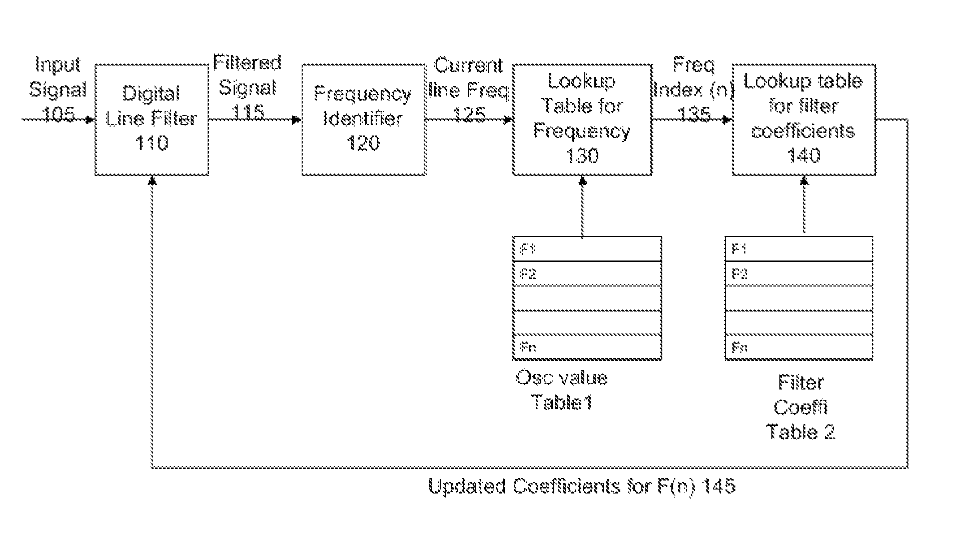
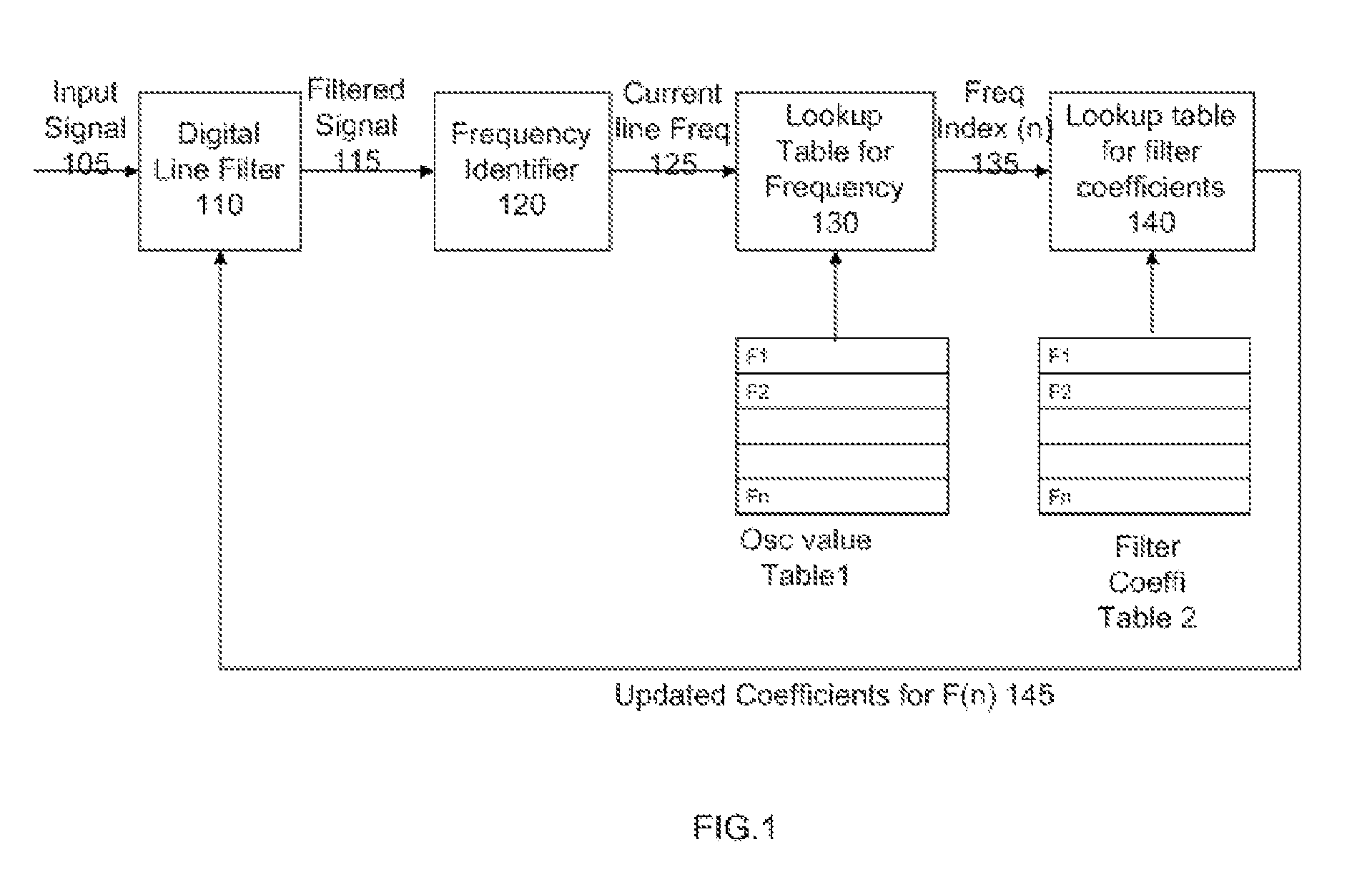
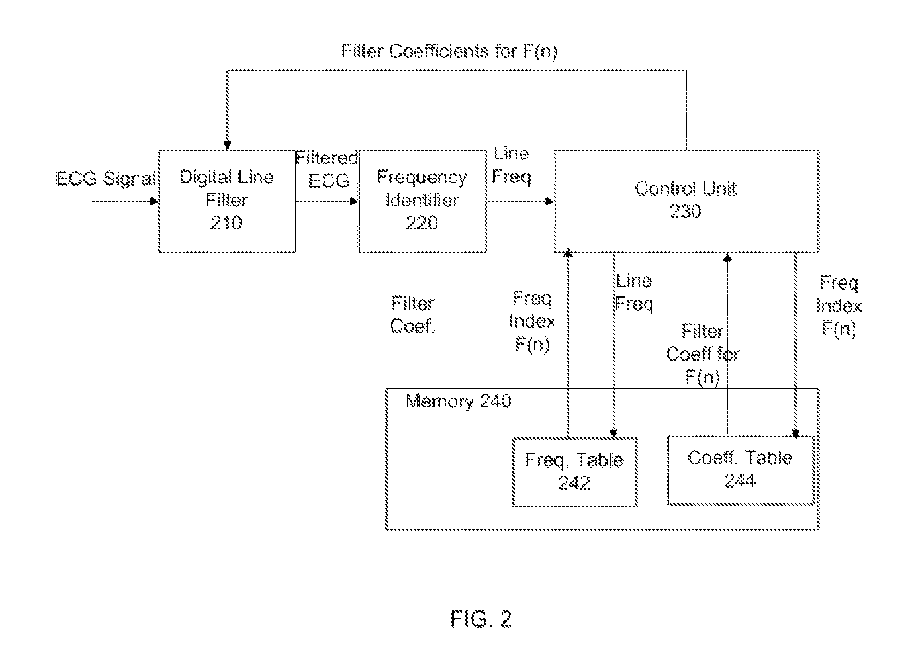
The present invention provides a method and system for filtering out power line interference from an ECG signal using a digital filter. The method involves identifying the current power line frequency, accessing a look up table to find the filter coefficients corresponding to it, and configuring the digital filter to filter the input signal. This enables accurate and effective removal of power line interference, improving the quality of ECG signals and ensuring reliable detection of ECG abnormalities. The technical effects of the invention include improved accuracy and reliability of ECG signal analysis, as well as improved performance of ECG devices in detecting abnormalities in ECG signals.

Problems solved by technology

The interference of noise signal on an ECG signal is significant as it may affect the quality of the signal and may result in wrong clinical interpretation.
One of the sources of the noise in the ECG signal is the power fluctuations and the interference from the power transmission line.
Thus clinically relevant information is lost from the ECG signal.
Some of the techniques for eliminating noise includes band limiting the signal to below the powerline frequency by using low pass filters, but this will result in loss of information since attenuation is done for all frequencies above 50 / 60 Hz.
Though this may be better option, using notch filters can cause ringing in the ECG waveform, which can result in wrong interpretation and analysis of the signal.
Some examples of adaptive filters studied, would filter the powerline frequency without affecting the ECG signal, but were not effective in the face of variations in frequency.

Method used


Image

  • Method and system for reducing power line interferences in an ECG signal
  • Method and system for reducing power line interferences in an ECG signal
  • Method and system for reducing power line interferences in an ECG signal

Examples


Embodiment Construction

[0017]In the following detailed description, reference is made to the accompanying drawings that form a part hereof, and in which is shown by way of illustration specific embodiments that may be practiced. These embodiments are described in sufficient detail to enable those skilled in the art to practice the embodiments, and it is to be understood that other embodiments may be utilized and that logical, mechanical, electrical and other changes may be made without departing from the scope of the embodiments. The following detailed description is, therefore, not to be taken as limiting the scope of the invention. To the extent that the figures illustrate diagrams of the functional blocks of various embodiments, the functional blocks are not necessarily indicative of the division between hardware circuitry. Thus, for example, one or more of the functional blocks (e.g., processors or memories) may be implemented in a single piece of hardware (e.g., a general purpose signal processor or ...


PUM


Abstract

A method and system for correcting power line interferences in an ElectroCardioGram (ECG) signal is disclosed. The method comprises: providing an input signal having ECG signal along with interference signals to a digital filter capable of filtering at a preset frequency and identifying current power line frequency, if any, from the filtered input signal. The method further includes providing a look up table with index number for a set of frequency levels and corresponding filter coefficients, the set of frequency includes incremental steps in the range of possible variations on the power line frequency. The filter coefficient corresponding to current power line frequency is identified from the look up table. The digital filter is configured using the identified filter coefficient and the input signal is filtered using the re-configured digital filter.

Description

FIELD OF INVENTION[0001]This invention relates generally to noise reduction techniques in an ECG device and more particularly to, a method and system for reducing power line interferences in an ECG signal.BACKGROUND OF INVENTION[0002]The interference of noise signal on an ECG signal is significant as it may affect the quality of the signal and may result in wrong clinical interpretation. One of the sources of the noise in the ECG signal is the power fluctuations and the interference from the power transmission line. Line frequency variation is common in many developing countries where ECG products are used for diagnostic purposes. Generally, the powerline frequency is expected to be 50 Hz or 60 Hz and this value is country specific. In some places the frequency varies from the set value.[0003]Some of the solutions suggest eliminating the noise in ECG signals, but at least a part of the ECG signal is also removed, while removing the noise. Thus clinically relevant information is lost...

Claims


Application Information

Patent Timeline
Patent Type & Authority Patents(United States)
IPC IPC(8): A61B5/0402A61B5/308
CPCH04B15/005A61B5/04017A61B5/0428A61B5/7203A61B5/316A61B5/30
Inventor MASCARENHAS, DINESH, LEO
Owner GENERAL ELECTRIC CO
Learn More