
Magnetic coupling assembly

a technology of magnetic couplings and assemblies, which is applied in the direction of mechanical equipment, machines/engines, liquid fuel engines, etc., can solve the problems that none of the prior art magnetic couplings described in the patent publications mentioned above can couple magnetic power exceeding 800 kw effect at 1800 rpm, and achieve the effects of improving reliability and coupling power, reducing the temperature of the magnetic coupling, and reducing the temperature of the coupling

Active Publication Date: 2020-09-17
FUGLESANGS SUBSEA
View PDF0 Cites 0 Cited by
  • Summary
  • Abstract
  • Description
  • Claims
  • Application Information

AI Technical Summary

Benefits of technology

The patent describes a magnetic coupling assembly for transferring power and torque without physical contact between parts. The assembly includes channels for cooling, stable operation, and flushing. The invention enables higher levels of power transfer and torque than previous technologies, and can transfer over 1 MW and 3600 rpm. It also improves coupling power reliability and increases the service life of the involved components. The magnetic coupling acts as a balancing drum and is modular for use in various systems and machines.

Problems solved by technology

None of the prior art magnetic couplings described in the patent publications mentioned above can couple magnetic power exceeding 800 kW effect at 1800 rpm.

Method used


Image

  • Magnetic coupling assembly
  • Magnetic coupling assembly
  • Magnetic coupling assembly

Examples


Embodiment Construction

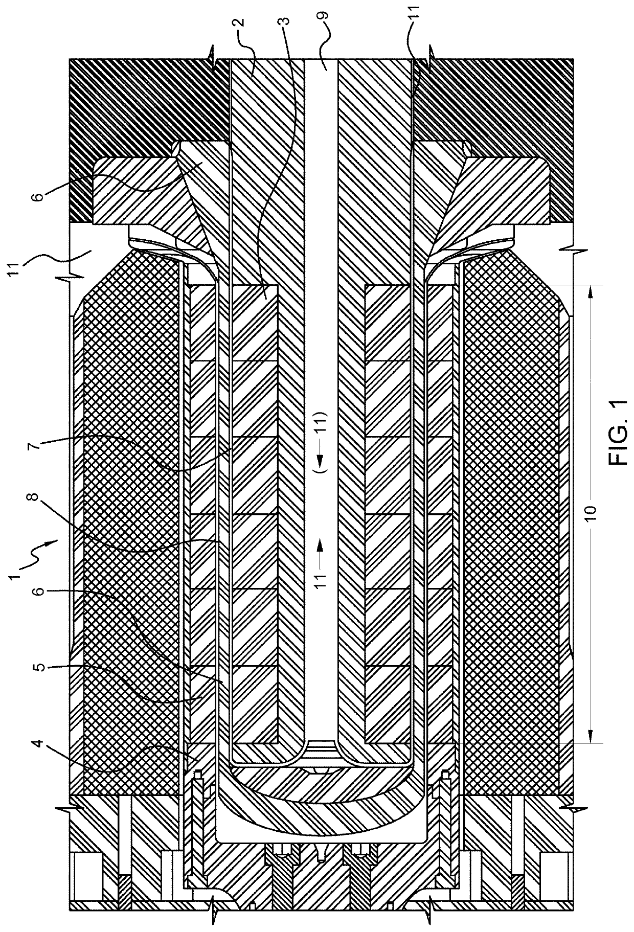
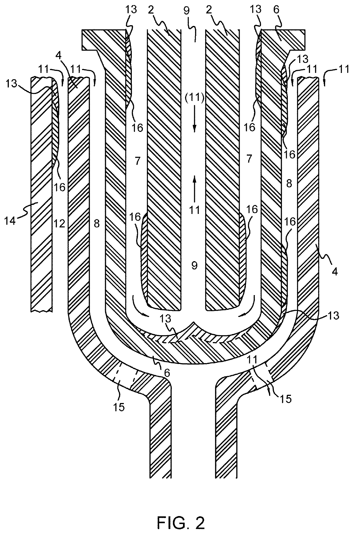
[0041]The sealing surfaces are non-contact sections of reduced cross section area or radial gap for flow. The radial gap clearance is preferably but not necessarily constant along the sealing surface section. The radial gap clearance in the sealing surface sections is less than else in the flow channel, typically about 0.1 mm to 2 mm, preferable 0.2-1.5 mm, 0.2-1.2 mm, or most preferable 0.4-1 mm. Normal radial channel clearance, in the magnetic coupling section, typically is 0.3 mm to 8 mm, more preferable 0.4-3 mm, 0.4-2.5 mm or most preferable 0.4-2 mm. The sealing surfaces are arranged within or outside the magnetic coupling section of the separation member, preferably just inside or outside the ends thereof. Preferably with a swirl breaker at the inlet, as seen in the direction of fluid flow.

[0042]The minimum radius of any part of the static separation member subject to load fluctuations, is Rmin=1 mm or 2 mm, more preferably 3 mm, even more preferably 5 mm.

[0043]Some further d...


PUM


Abstract

The invention provides a magnetic coupling assembly (1), comprising: a rotatable male coupling member (2) comprising magnets (3); a rotatable female coupling member (4) comprising magnets (5); a static separation member (6) arranged between the male and female coupling members, a first channel (7) in a gap between the male coupling member and the separation member, a second channel (8) in a gap between the female coupling member and the separation member, an axial internal channel (9) in the male coupling member, a magnetic coupling section (10) of the static separation member, wherein said magnetic coupling section is the section of the static separation member between the magnets of the male coupling member and the magnets of the female coupling member, wherein the female and male coupling members are rotatable coupled by the magnets through the magnetic coupling section of the static separation member. The magnetic coupling assembly is distinguished in that: the first channel, the second channel and the axial

Description

TECHNICAL FIELD[0001]The present invention relates to magnetic couplings and machines comprising magnetic couplings.BACKGROUND ART[0002]A demand exists for higher power, lower cost per power or effect coupled for magnetic couplings. The state of the art magnetic coupling, as far as known by the applicant, is described and illustrated in the patent publication U.S. Pat. No. 8,956,067 B2, in the name of Ruhrpumpen GmbH. With the magnetic coupling of said patent, it is possible to couple magnetically up to 800 kW effect or power, at 1800 rpm (rotations per minute). Other embodiments of magnetic couplings are described and illustrated in the patent publications US 2015 / 0322756 A1, US 2015 / 0270768 A1, DE 3413930 A1, WO 2014 / 109648 A1 and US 2011 / 0057456 A1.[0003]None of the prior art magnetic couplings described in the patent publications mentioned above can couple magnetic power exceeding 800 kW effect at 1800 rpm.SUMMARY OF INVENTION[0004]The invention provides a magnetic coupling asse...

Claims


Application Information

Patent Timeline
IPC IPC(8): F04D13/02
CPCF04D13/024F04D25/026F04D29/026F04D29/047F04D29/057F04D29/584F04D29/588F16L23/16H02K49/106H02K49/104
Inventor FUGLESANG, ALEXANDERWESTBERG, TOMMYNAVJORD, THOMASAAS, MARIUS KRUSE
Owner FUGLESANGS SUBSEA
Learn More