
Integrated Optical Fiber and Epsilon-Near-Zero Material

a technology of optical fiber and epsilon-near-zero material, applied in the field of optical fiber, can solve the problems of poor electronic, magneto-optical, nonlinear-optical response, and limited functionality of the excitation platform

Active Publication Date: 2020-09-10
BAYLOR UNIVERSITY
View PDF0 Cites 3 Cited by
  • Summary
  • Abstract
  • Description
  • Claims
  • Application Information

AI Technical Summary

Benefits of technology

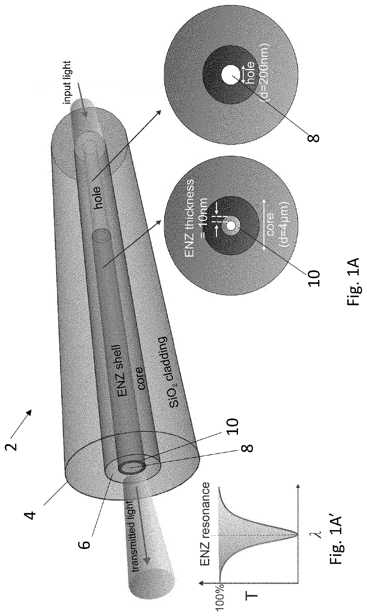
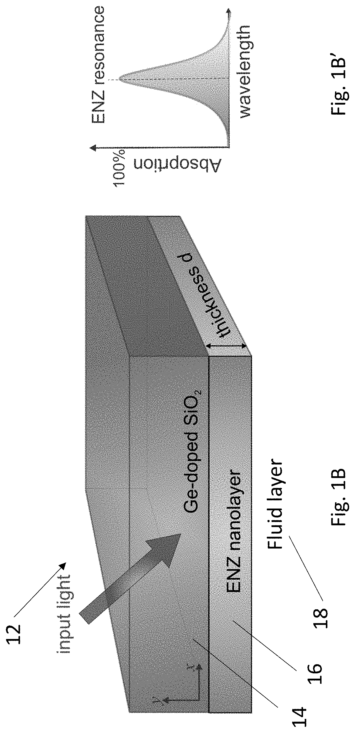
This patent presents a design for an optical fiber that includes a thin layer of epsilon-near-zero (ENZ) material. This design results in the excitation of a highly confined waveguide mode in the fiber near the wavelength where the ENZ material has a very low permittivity. This in-fiber excitation of the ENZ mode is caused by the coupling of the guided fundamental core mode to the thin-film ENZ mode. The ENZ nanostructured optical fibers have many potential applications, such as in nonlinear and magneto-optics, as in-fiber wavelength-dependent filters, and as subwavelength fluid channel for optical and bio-photonic sensing. The disclosed optical fibers include a nanobore fiber, an anti-resonance hollow core optical fiber, and an optical fiber with D-shaped platform. The patent also describes a method of manufacturing and using the optical fiber.

Problems solved by technology

However, most of the studies on ENZ optical properties are limited to the excitation of ENZ mode in the planar structures or meta-surfaces with short interaction length, restricting the excitation platform.
Although a dielectric optical waveguide is very efficient in transmitting light, its functionality is somewhat limited by the dielectric material of the core, which has poor electronic, magneto-optical, and nonlinear-optical responses and has the dielectric diffraction limit.
Therefore, the optical properties of the optical fiber waveguide such as phase, amplitude, polarization state, and mode profile cannot be altered after the fiber drawing fabrication.

Method used


Image

  • Integrated Optical Fiber and Epsilon-Near-Zero Material
  • Integrated Optical Fiber and Epsilon-Near-Zero Material
  • Integrated Optical Fiber and Epsilon-Near-Zero Material

Examples


Embodiment Construction

[0066]The Figures described above and the written description of specific structures and functions below are not presented to limit the scope of what Applicant has invented or the scope of the appended claims. Rather, the Figures and written description are provided to teach any person skilled in the art to make and use the inventions for which patent protection is sought. Those skilled in the art will appreciate that not all features of a commercial embodiment of the inventions are described or shown for the sake of clarity and understanding. Persons of skill in this art will also appreciate that the development of an actual commercial embodiment incorporating aspects of the present disclosure will require numerous implementation-specific decisions to achieve the developer's ultimate goal for the commercial embodiment. Such implementation-specific decisions may include, and likely are not limited to, compliance with system-related, business-related, government-related, and other co...


PUM

PropertyMeasurementUnit
thicknessesaaaaaaaaaa

Abstract

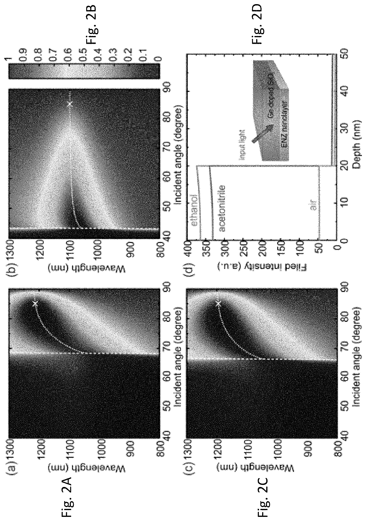
The present disclosure provides an optical waveguide design of a fiber modified with a thin layer of epsilon-near-zero (ENZ) material. The design results in an excitation of a highly confined waveguide mode in the fiber near the wavelength where permittivity of thin layer approaches zero. Due to the high field confinement within thin layer, the ENZ mode can be characterized by a peak in modal loss of the hybrid waveguide. Results show that such in-fiber excitation of ENZ mode is due to the coupling of the guided fundamental core mode to the thin-film ENZ mode. The phase matching wavelength, where the coupling takes place, varies depending on the refractive index of the constituents. These ENZ nanostructured optical fibers have many potential applications, for example, in ENZ nonlinear and magneto-optics, as in-fiber wavelength-dependent filters, and as subwavelength fluid channel for optical and bio-photonic sensing.

Description

CROSS REFERENCE TO RELATED APPLICATIONS[0001]This application claims the benefit of U.S. Provisional Ser. No. 62 / 800,806, filed Feb. 4, 2019, entitled “Integrated Optical Fiber and Epsilon-Near-Zero Material”, which is incorporated herein by reference.[0002]STATEMENT REGARDING FEDERALLY SPONSORED RESEARCH OR DEVELOPMENT[0003]Not applicable.REFERENCE TO APPENDIX[0004]Not applicable.BACKGROUND OF THE INVENTIONField of the Invention[0005]The disclosure generally relates to optical fiber. More specifically, the disclosure relates to optical fiber integrated with epsilon-near-zero capable materials that affects the performance characteristics of the optical fiber.Description of the Related Art[0006]Optical response of near-zero refractive index systems has been a topic of interest recently as the electromagnetic field inside the media with near-zero parameters, such as vanishing permittivity and permeability values, have been shown to exhibit unique optical properties. Those features may...

Claims


Application Information

Patent Timeline
Patent Type & Authority Applications(United States)
IPC IPC(8): G02B6/02G02B6/27
CPCG02B6/2746G02B6/02028G02B6/02295G02B6/105G02B1/002G02B6/02G02B6/0229G02B6/02328G02B6/02366G02B6/02347
Inventor LEE, HO WAI HOWARDMINN, KHANTYANG, JINGYIANOPCHENKO, OLEKSIY
Owner BAYLOR UNIVERSITY
Learn More