Luminaire with Changeable Beam Angle and Fixed Center Beam Candle Power

a technology of fixed center beam and changeable beam angle, which is applied in the direction of instruments, lighting and heating apparatus, semiconductor devices for light sources, etc., can solve the problems of affecting the appearance of antiques in museums, affecting the work environment, and affecting the effect of lighting

Active Publication Date: 2020-09-10
LEDVANCE GMBH
View PDF0 Cites 6 Cited by
  • Summary
  • Abstract
  • Description
  • Claims
  • Application Information

AI Technical Summary

Benefits of technology

[0013]Further, it is possible to adjust the luminous flux emitted by the light source in a way to keep the center beam candle power (CBCP) essentially constant and independent from the beam angle. In a setting of the beam angle adjustment mechanism where the beam angle is minimal (i.e., the smallest beam angle possible for the lighting device), the luminous flux emitted by the light source will be reduced as all of the light emitted by the lighting device will be concentrated in a small area. On the other hand, in a setting of the beam angle adjustment mechanism where the beam angle is maximal (i.e., the largest beam angle possible for the lighting device), the luminous flux emitted by the light source will be increased as all of the light emitted by the lighting device will be spread out over a larger area.
[0019]In an embodiment, the first component and the second component of the beam angle adjustment mechanism are threadedly engaged with each other. The first component and the second component may both have an essentially tubular shape, with a first thread on the outside of one of the two components and a second thread, corresponding to the first thread on the inside of the other one of the two components. Rotating the two components with respect to each other results in a telescoping movement and, thus, may change the distance between light source and beam shaping element. The beam shaping element in this embodiment may be a lens held by one of the two components of the beam angle adjustment mechanism. The other component may be attached to the housing holding the light source or be an integral part thereof.

Problems solved by technology

This may be especially undesirable for workplaces.
This may be dangerous as persons within the light beam might be blinded.
It may also be possible that antiques in a museum may become damaged if the CBCP gets too high.

Method used


Image

  • Luminaire with Changeable Beam Angle and Fixed Center Beam Candle Power
  • Luminaire with Changeable Beam Angle and Fixed Center Beam Candle Power
  • Luminaire with Changeable Beam Angle and Fixed Center Beam Candle Power

Examples


Embodiment Construction

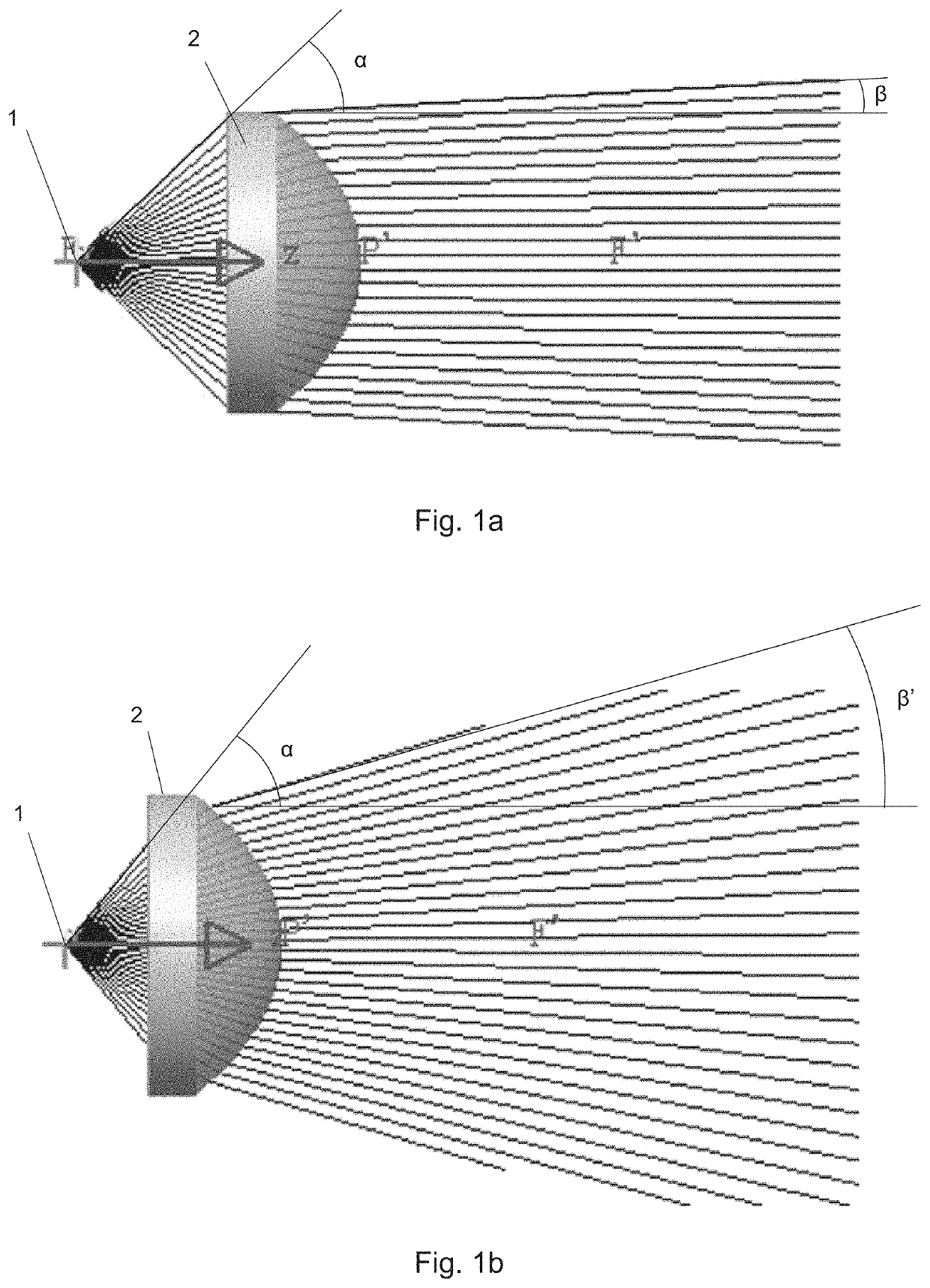
[0039]In the following, preferred embodiments of the invention will be described with reference to the drawings. The same or similar elements or elements having the same effect may be indicated by the same reference number in multiple drawings. Repeating the description of such elements may be omitted in order to prevent redundant descriptions.

[0040]FIGS. 1a and 1b depict schematically the change in beam angle depending on a distance between light source and beam shaping element. The drawings show a light source 1 (such as an LED) emitting light in a cone with a first angle a around a main direction z. The emitted light is incident on a beam shaping element in the form of a lens 2. The lens 2 shown in these drawings is a plano-convex lens, but other types of lenses may also be used. The lens 2 collimates the beam of light emitted by the light source 1 such that the beam exiting the lens 2 has a smaller angle β or β′ depending on the distance of the light source 1 from the lens 2.

[00...


PUM


Abstract

A lighting device with changeable beam angle and fixed center beam candle power. The device may include a light source, an electronic driver for driving the light source to emit light, a beam shaping element for shaping a beam of light emitted by the light source, a beam angle adjustment mechanism configured to change a positional relationship between the light source and the beam shaping element, and a sensor configured to provide a signal indicative of a setting of the beam angle adjustment mechanism. The electronic driver is configured to adjust the luminous flux emitted by the light source depending on the signal provided by the sensor. Such a lighting device may keep the center beam candle power of the emitted light constant when the beam angle is changed.

Description

CROSS-REFERENCE TO RELATED APPLICATIONS[0001]This application claims the benefit of CN Application No. 201910167505.X filed Mar. 6, 2019, which is hereby incorporated by reference herein in its entirety.TECHNICAL FIELD[0002]The present invention relates to a luminaire with changeable beam angles and fixed center beam candle power.BACKGROUND[0003]Two important parameters of luminaires are the beam angle of the emitted light and the center beam candle power (CBCP). Center beam candle power is the luminous intensity along the geometric centerline of a directional light source. Usually, the center beam candle power (often also written as center beam candlepower) is also the maximum candlepower. The center beam candle power is also called center-beam intensity.[0004]In luminaires with a fixed beam angle, the CBCP usually is also fixed.[0005]In luminaires having a changeable beam angle, the CBCP usually changes when the beam angle is changed. For example, when the beam angle is increased,...

Claims


Application Information

Patent Timeline
Patent Type & Authority Applications(United States)
IPC IPC(8): F21V23/04F21V23/00F21V14/06F21S6/00F21V23/02
CPCF21S6/003G01D5/244F21V23/003G01D5/3473F21V14/06F21Y2115/10F21V23/02F21V23/0492F21K9/20F21V5/04F21V7/00F21V23/0442F21V14/02F21V14/04F21V17/02
Inventor LUO, JINHUILI, ZHIANDENG, JIANXIONG
Owner LEDVANCE GMBH
Why Eureka
Try Eureka