
Electric stapler

a stapler and electric technology, applied in the field of office stationery, can solve the problems of manual paper punching, inconvenient use, and the inability of electric staplers to adjust the binding distance, and achieve the effects of good strength, stable transmission, and large transmission torqu

Inactive Publication Date: 2020-09-10
EAGLE SHAOGUAN STATIONERY TECH LTD
View PDF0 Cites 0 Cited by
  • Summary
  • Abstract
  • Description
  • Claims
  • Application Information

AI Technical Summary

Benefits of technology

The present invention is an electric stapler that solves issues in the prior art. It includes a distance adjusting block and planetary gears that provide strong transmission torque, stability, and low noise. The stapler has a simple mechanism with a sliding frame and cam, and damping rubbers ensure a stable and reliable stapling process. The binding mechanism also includes a power-off protection design to prevent injury or damage.

Problems solved by technology

The staplers commonly used on the market generally require manual paper-punching, which are not convenient in use.
The current electric staplers do not allow the adjustment of the binding distance of the paper edge while the existing electric staplers are mostly of the complicated spur gear structure, which generates much noise and are instable in functioning.

Method used


Image

  • Electric stapler
  • Electric stapler
  • Electric stapler

Examples


embodiment 1

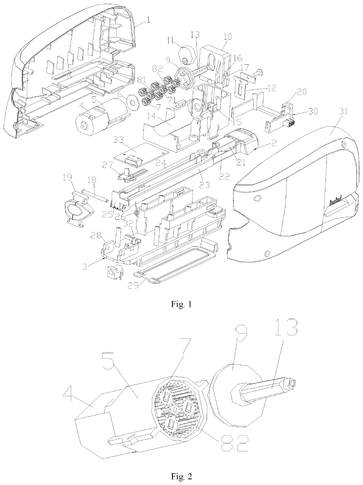
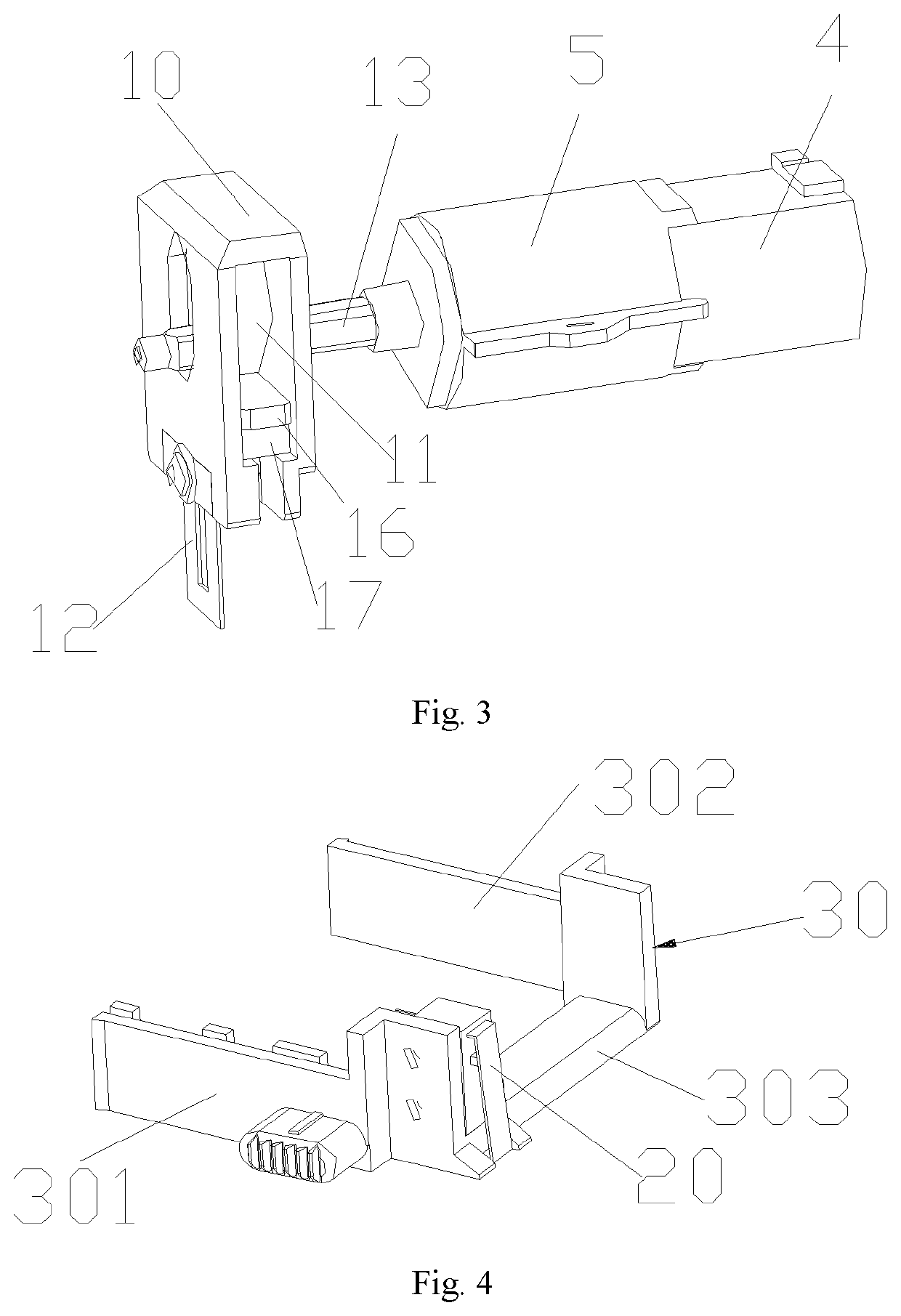
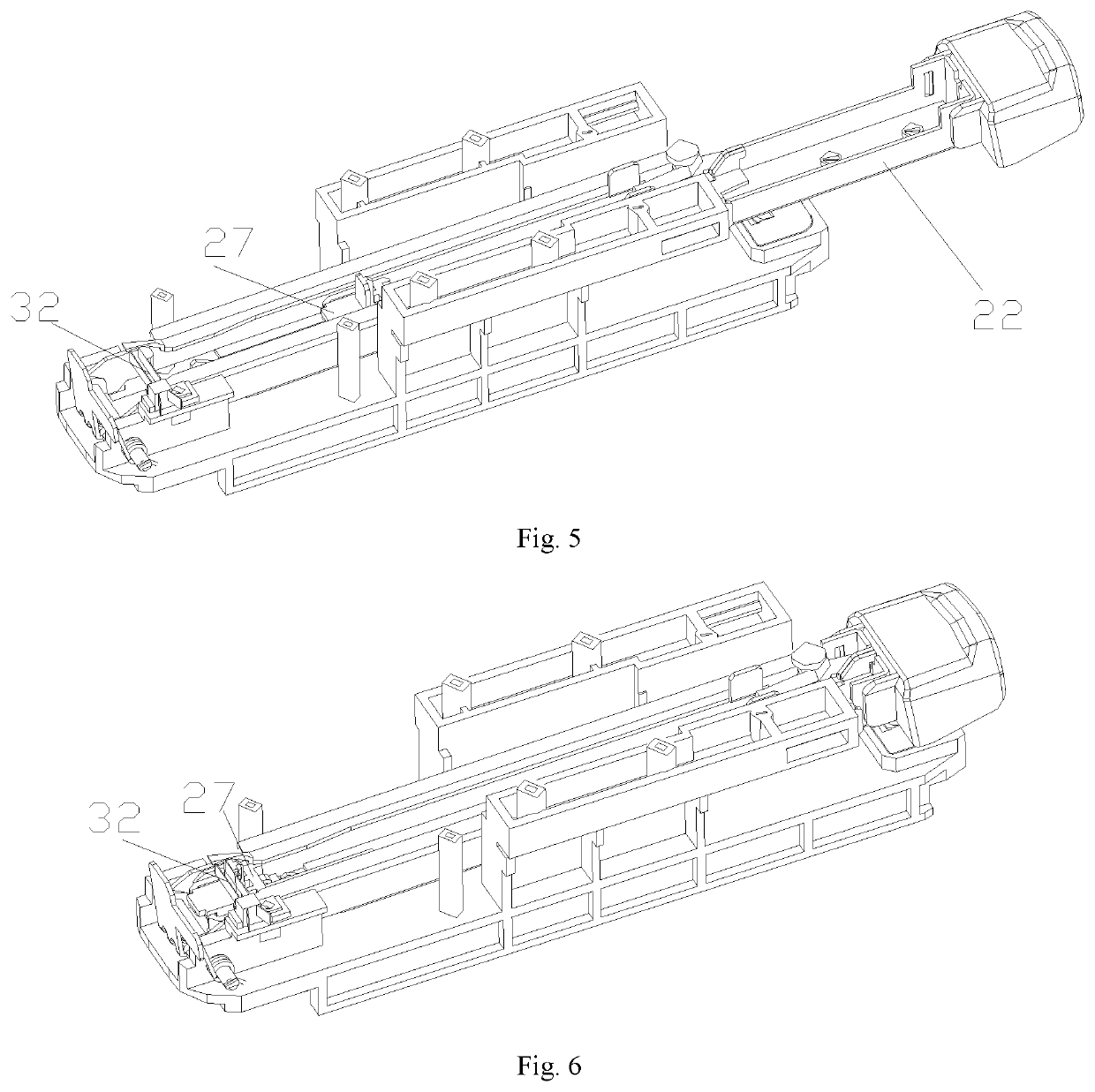
[0034]As shown in FIGS. 1 to 6, the embodiment provides an electric stapler, comprising a left cover 1 and a right cover 31, wherein an accommodation space is formed when said left cover 1 and the right cover 31 buckle together, and it further comprises:

[0035]A binding mechanism, wherein said binding mechanism comprises a base 3 and a binding frame 2 and the back ends of said base 3 and the binding frame 2 are rotatably connected by a pivot 18;

[0036]A pressing mechanism, wherein said pressing mechanism is disposed above the front end of the binding frame 2 for driving the binding mechanism to complete the binding;

[0037]A driving mechanism, wherein said driving mechanism is disposed above the binding mechanism, said driving mechanism is connected to said pressing mechanism through a transmission shaft 13, and said driving mechanism is used to drive the pressing mechanism to move up and down;

[0038]A distance adjusting block 30, wherein said distance adjusting block 30 is of a U-shaped...


PUM


Abstract

The present invention relates generally to the technical field of office stationery. More particularly, it relates to an electric stapler comprising a left cover and a right cover, wherein an accommodation space is formed when said left and right covers buckle together. Inside the accommodation space, there disposes a driving mechanism, a pressing mechanism, a control mechanism, a binding mechanism, a circuit board and a distance adjusting block, wherein said driving mechanism is connected to said pressing mechanism through a transmission shaft for driving the pressing mechanism to move up and down; said binding mechanism is disposed under the driving mechanism and the pressing mechanism, said distance adjusting block is disposed on the binding mechanism in front of the staple outlet, and the paper feeding switch in sais control mechanism is disposed on the distance adjusting block. The present invention can change the distance from the staple outlet to the paper feeding switch with the distance adjusting block, thereby adjusting the binding distance of the paper edge to meet different requirements on binding margin

Description

TECHNICAL FIELD[0001]The present invention relates generally to the technical field of office stationery. More particularly, it relates to an electric stapler.STATE OF THE PRIOR ART[0002]The staplers commonly used on the market generally require manual paper-punching, which are not convenient in use. Therefore, in order to eliminate the inconvenience of manual stapler in use, electric stapler is introduced to the market. The current electric staplers do not allow the adjustment of the binding distance of the paper edge while the existing electric staplers are mostly of the complicated spur gear structure, which generates much noise and are instable in functioning.SUMMARY OF THE INVENTION[0003]It is an object the present invention is to provide an electric stapler as a solution to the deficiencies in the prior art, which adjusts the binding distance of the paper edge with a distance adjusting block and adopts planetary gear and sliding stapling structures, enabling the electric stapl...

Claims


Application Information

Patent Timeline
Patent Type & Authority Applications(United States)
IPC IPC(8): B25C7/00B25C5/15
CPCB25C5/15B25C7/00
Inventor CHAN, SIU LEUNGXIONG, HUIXIONGCHEN, GUANTAI
Owner EAGLE SHAOGUAN STATIONERY TECH LTD
Learn More