Display device
a display device and display technology, applied in non-linear optics, instruments, optics, etc., can solve problems such as difficulty in narrowing the frame area of the display
- Summary
- Abstract
- Description
- Claims
- Application Information
AI Technical Summary
Benefits of technology
Problems solved by technology
Method used
Image

Examples
embodiment 1
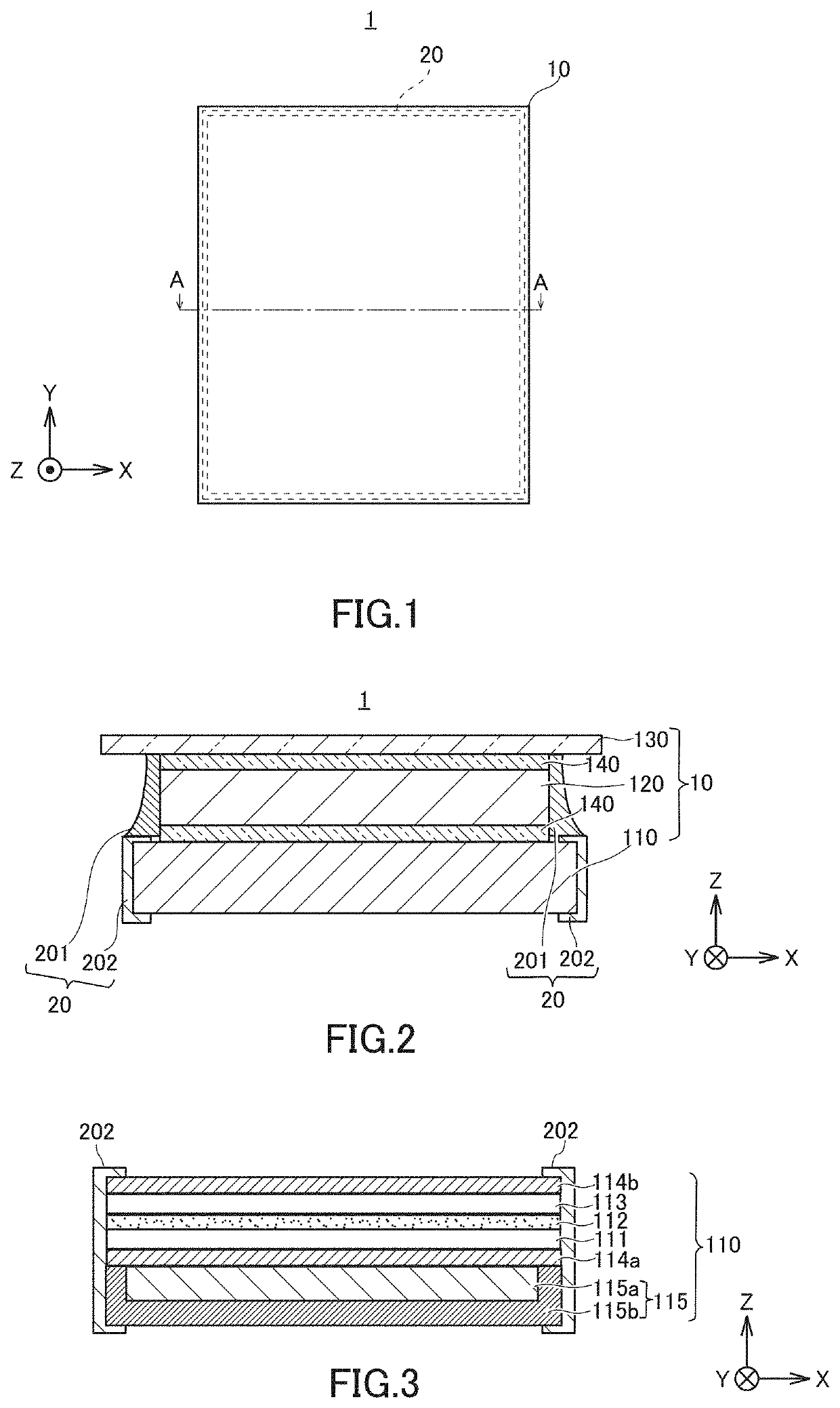
[0018]FIG. 1 is a schematic plan view illustrating a schematic configuration of a display device according to the present embodiment. The display device 1 is a so-called touch-panel-equipped display device that has an image displaying function of displaying an image, and a touch detecting function of detecting a touch position that is a position touched by a user.
[0019]The display device 1 includes a touch-panel-equipped display module 10 that includes a touch panel, and an electrostatic protection member 20. The electrostatic protection member 20 is provided along side surfaces of the touch-panel-equipped display module 10. The following description describes the touch-panel-equipped display module 10 and the electrostatic protection member 20 more specifically.
(Configuration of Touch-Panel-Equipped Display Module 10)
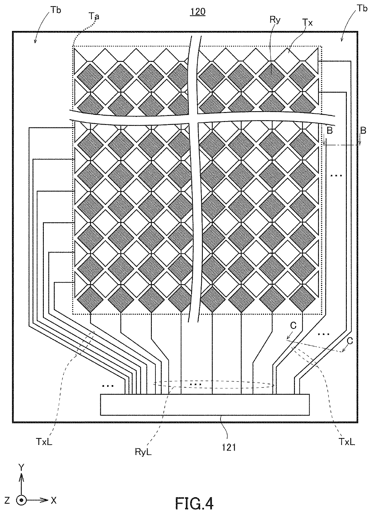
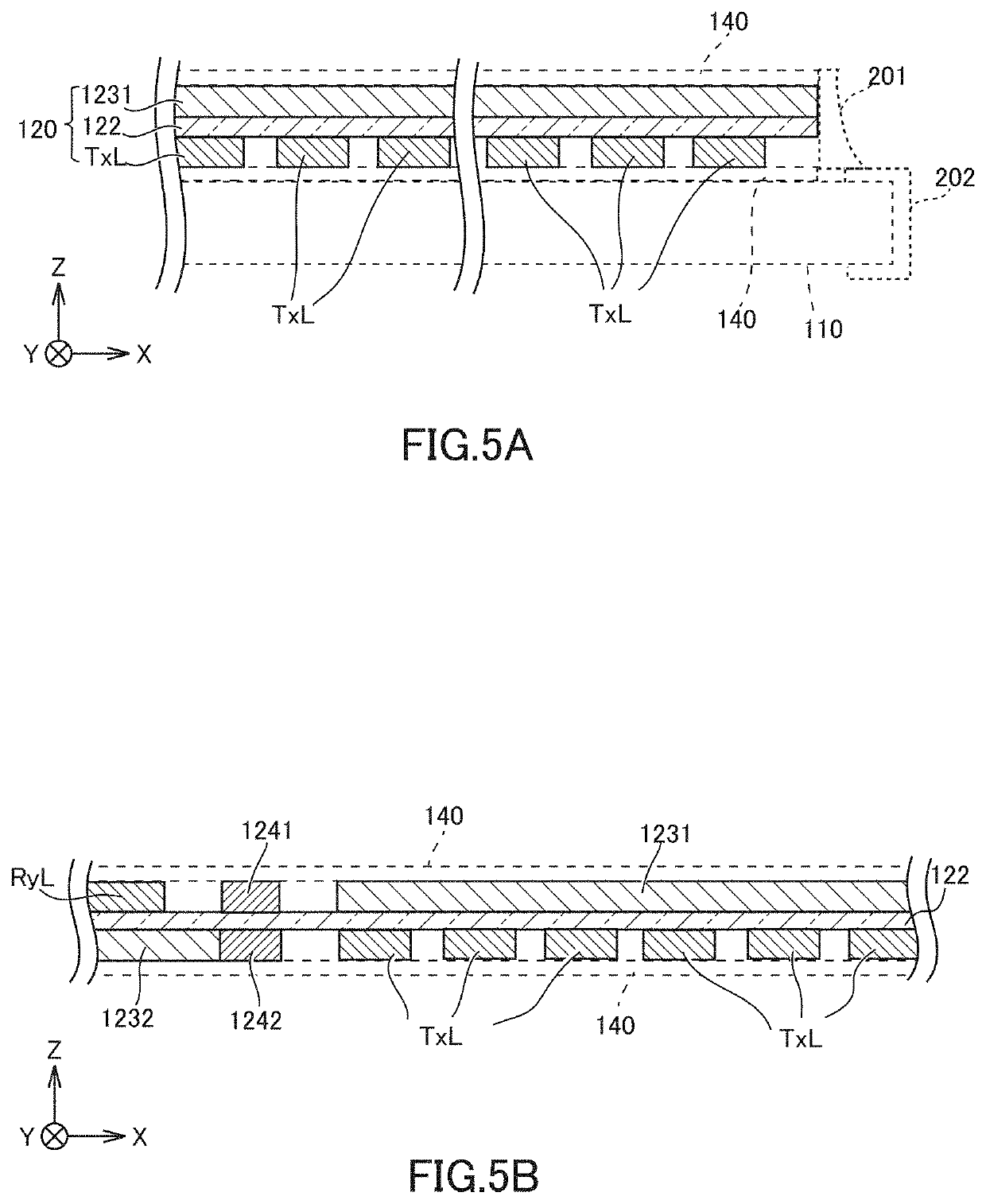
[0020]FIG. 2 is a schematic cross-sectional view of the display device 1 illustrated in FIG. 1, taken along line A-A. As illustrated in FIG. 2, the touch-panel-equippe...
embodiment 2
[0053]The present embodiment is described with reference to an exemplary electrostatic protection member having a configuration different from that in Embodiment 1 described above. FIG. 6 is a cross-sectional view illustrating a schematic configuration of a touch-panel-equipped display module in the present embodiment. In FIG. 6, the same constituent members as those in Embodiment 1 are denoted by the same reference symbols as those in Embodiment 1.
[0054]As illustrated in FIG. 6, a touch-panel-equipped display module 10a in the present embodiment includes an electrostatic protection member 20A. The electrostatic protection member 20A is different from the electrostatic protection member in Embodiment 1 in the point that the electrostatic protection member 20A covers an entirety of the side surfaces of the touch panel 120, but does not cover an entirety of the side surfaces of the display module 110. Further, the electrostatic protection member 20A is different from the electrostatic...
embodiment 3
[0069]Embodiments 1 and 2 described above are described with reference to a display device where the touch panel 120 is arranged on the display module 110, but the display device may be without the touch panel 120. The following description describes an exemplary display device in the present embodiment.
[0070]FIG. 8 is a schematic cross-sectional view illustrating a display device in the present embodiment. In FIG. 8, the same constituent members as those in Embodiment 1 are denoted by the same reference symbols as those in Embodiment 1.
[0071]As illustrated in FIG. 8, a display device 1 B is different from the display device 1 of Embodiment 1 in the point that the touch panel 120 (see FIG. 2), and the adhesive layer 140 (see FIG. 2) between the touch panel 120 and the cover glass 130, are not provided on the display module 110.
[0072]In the display device 1B, an electrostatic protection member 20B is composed of a first protection member 211 and a second protection member 212. The fi...
PUM
| Property | Measurement | Unit |
|---|---|---|
| conductive | aaaaa | aaaaa |
| conductivity | aaaaa | aaaaa |
| size | aaaaa | aaaaa |
Abstract
Description
Claims
Application Information
 - R&D
- Intellectual Property
- Life Sciences
- Materials
- Tech Scout
- Unparalleled Data Quality
- Higher Quality Content
- 60% Fewer Hallucinations
Browse by: Latest US Patents, China's latest patents, Technical Efficacy Thesaurus, Application Domain, Technology Topic, Popular Technical Reports.
© 2025 PatSnap. All rights reserved.Legal|Privacy policy|Modern Slavery Act Transparency Statement|Sitemap|About US| Contact US: help@patsnap.com