Heat exchanger

Active Publication Date: 2020-08-27
AURAS TECH
View PDF0 Cites 1 Cited by
  • Summary
  • Abstract
  • Description
  • Claims
  • Application Information

AI Technical Summary

Benefits of technology

The present invention provides a heat exchanger with improved heat dissipation performance. By using two gas conduits, the gas can be quickly transferred to the heat exchanger and distributed to multiple heat exchanger tubes for cooling down. This results in a faster heat exchanger response time and better heat dissipation performance.

Problems solved by technology

However, the amount of heat to be removed by the water-cooling heat exchanger is limited.

Method used


Image

  • Heat exchanger
  • Heat exchanger
  • Heat exchanger

Examples


Embodiment Construction

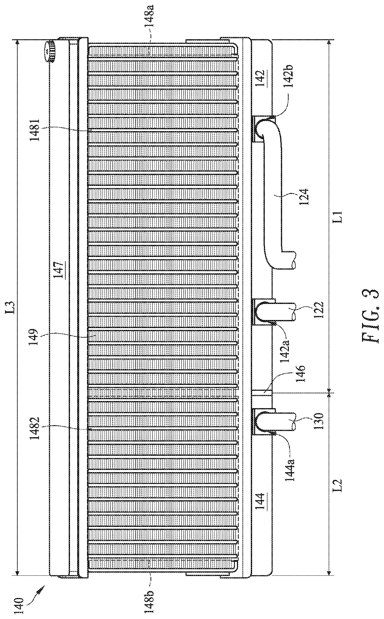
[0021]FIG. 1 is a schematic perspective view illustrating a heat exchanger according to an embodiment of the present invention. As shown in FIG. 1, the heat exchanger 100 comprises a heat-absorbing part 110, at least two gas conduits 122, 124, a return conduit 130 and a condensing part 140. A loop is defined by the heat-absorbing part 110, the at least two gas conduits 122, 124, the condensing part 140 and the return conduit 130 collaboratively. Moreover, a working medium is filled in the loop. Initially, the working medium is in a liquid state. After the working medium absorbs heat, the working medium is transformed to a gaseous state to carry away a great amount of heat. In an embodiment, the working medium is water or an engineered fluid with a low boiling point. For example, the working medium is 3M Fluorinert FC-72 (boiling point is 56 C), 3M Novec Fluids 7000 (boiling point is 34 C) or 3M Novec Fluids 7100 (boiling point is 61 C). As long as the working medium is transformed i...


PUM


Abstract

A heat exchanger includes a heat-absorbing part, two gas conduits, a return conduit and a condensing part. The heat-absorbing part includes a gas zone and a liquid zone. The heat-absorbing part includes a gas zone and a liquid zone. A first end of each gas conduit is connected with the gas zone of the heat-absorbing part. A first end of the return conduit is connected with the liquid zone of the heat-absorbing part. The condensing part includes a gas-inputting chamber, a liquid-outputting chamber, a partition plate, a communication chamber, a first condenser tube group and a second condenser tube group. The gas-inputting chamber is connected with a second end of each gas conduit. The liquid-outputting chamber is connected with a second end of the return conduit. A loop is defined by the heat-absorbing part, the at least two gas conduits, the return conduit and the condensing part collaboratively.

Description

FIELD OF THE INVENTION[0001]The present invention relates to a heat exchanger.BACKGROUND OF THE INVENTION[0002]A conventional water-cooling heat exchanger comprises a water-cooling head, a water-cooling radiator, a fan and a pump, which are in communication with each other through a piping system to define a loop. Moreover, water is filled in the loop. During the operation of the water-cooling heat exchanger, the heated water is transferred from the water-cooling head to the water-cooling radiator and the temperature of the water is decreased by the fan and fins. In addition, the water is returned back to the water-cooling head by the pump.[0003]However, the amount of heat to be removed by the water-cooling heat exchanger is limited. Therefore, the heat exchanger needs to be further improved.SUMMARY OF THE INVENTION[0004]For overcoming the drawbacks of the conventional technologies, the present invention provides a heat exchanger with enhanced heat dissipation performance.[0005]In a...

Claims


Application Information

Patent Timeline
IPC IPC(8): F25B39/04F28D7/00
CPCF28D7/0066F25B39/04F28D1/0443F28D1/05375F28D15/0266H01L23/427
Inventor CHEN, CHIEN-ANCHEN, CHIEN-YUYE, TIAN-LI
Owner AURAS TECH
Why Eureka
Try Eureka