Park Lock for an Automatic Transmission in a Motor Vehicle

Active Publication Date: 2020-08-06
ZF FRIEDRICHSHAFEN AG
View PDF0 Cites 3 Cited by
  • Summary
  • Abstract
  • Description
  • Claims
  • Application Information

AI Technical Summary

Benefits of technology

The invention is about a parking lock for a motor vehicle that includes a parking interlock gear and a locking pawl. A spring and a hydraulically actuatable actuator act on the locking pawl to engage or disengage the parking lock. A connecting bar is connected to a selector lever, which is pivotally mounted on a pawl pin. The connecting bar has an interlocking element that engages with tooth spaces of the parking interlock gear to prevent rotation of the transmission shaft. A hold-down spring prevents the locking pawl from touching the parking interlock gear when the parking lock is disengaged. The invention provides a compact and robust design with minimal friction effects and prevents rattling of the locking pawl.

Problems solved by technology

In the event of a failure of the electrohydraulic transmission control unit, it is no longer possible, however, to once again release the, generally, form-fit mechanical detent via the electromagnet, since the electrical control is disabled.

Method used


Image

  • Park Lock for an Automatic Transmission in a Motor Vehicle
  • Park Lock for an Automatic Transmission in a Motor Vehicle
  • Park Lock for an Automatic Transmission in a Motor Vehicle

Examples


Embodiment Construction

[0038]Reference will now be made to embodiments of the invention, one or more examples of which are shown in the drawings. Each embodiment is provided by way of explanation of the invention, and not as a limitation of the invention. For example, features illustrated or described as part of one embodiment can be combined with another embodiment to yield still another embodiment. It is intended that the present invention include these and other modifications and variations to the embodiments described herein.

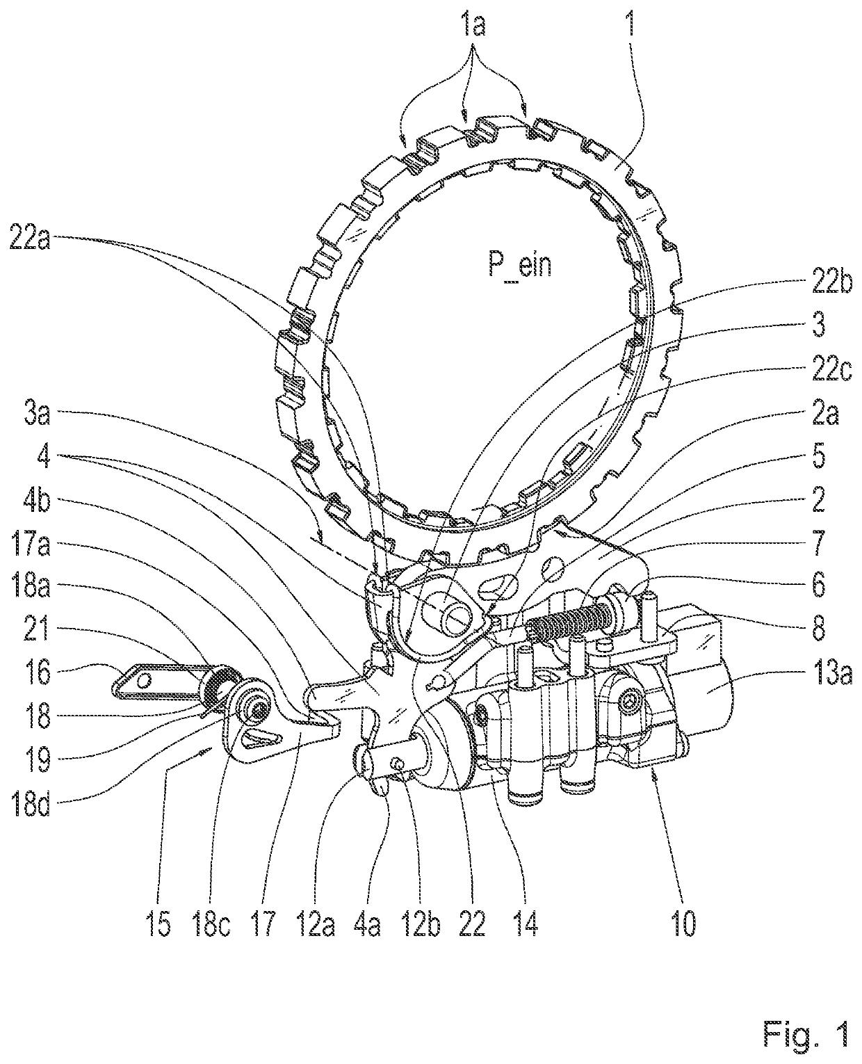
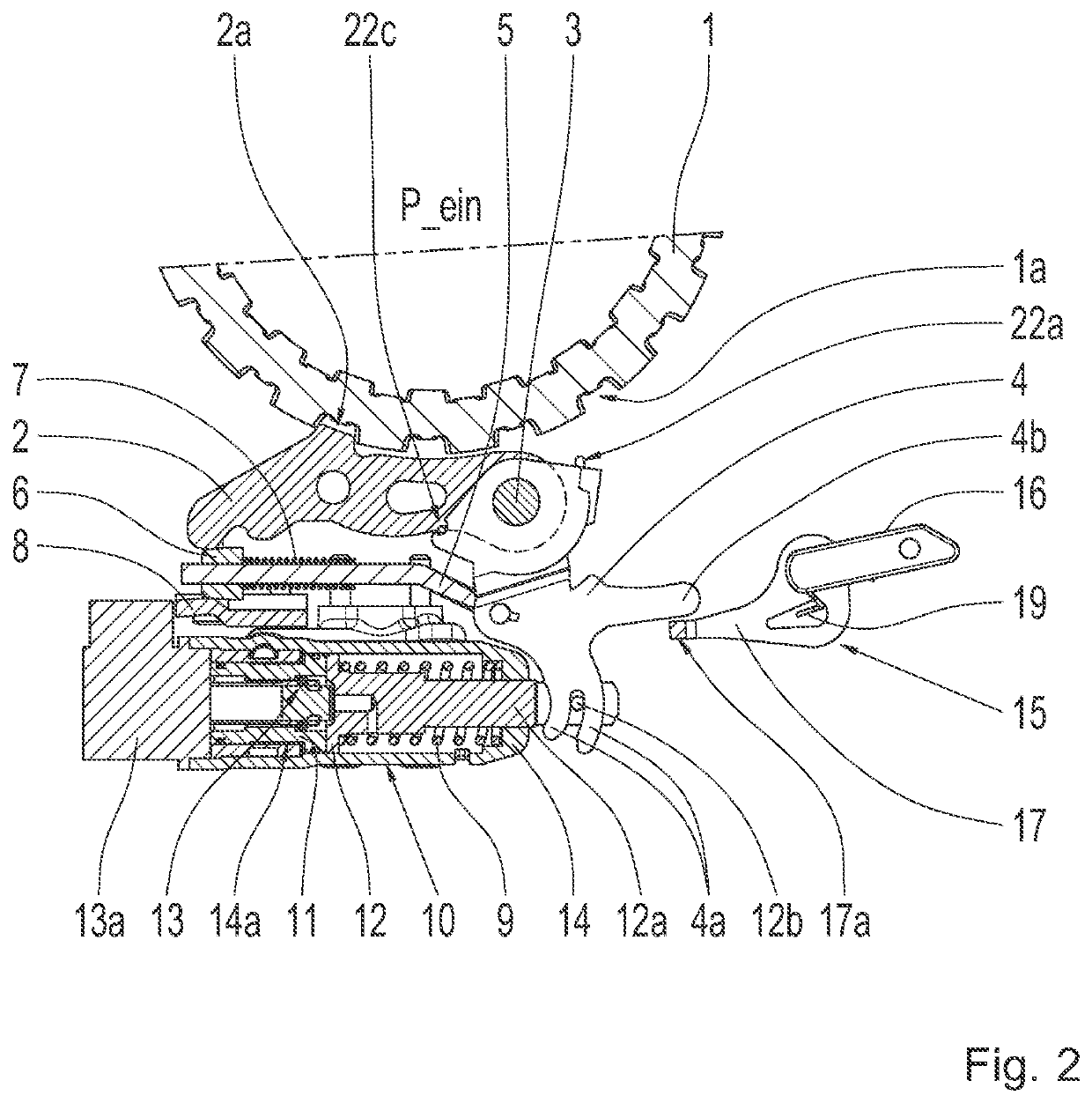
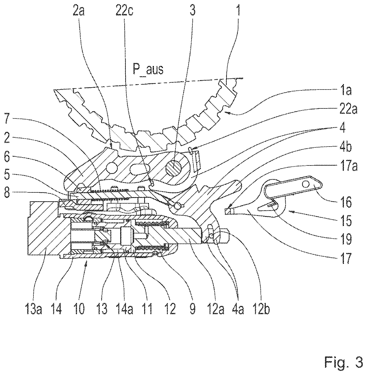
[0039]A preferred first exemplary embodiment of a parking lock according to example aspects of the invention for an automatic transmission of a motor vehicle is described in greater detail in the following and with reference to FIGS. 1 through 5. FIG. 1 shows a three-dimensional representation of the parking lock in the “parking lock engaged” engagement position, marked by the reference character P_ein. FIG. 2 shows a corresponding section view of the parking lock. FIG. 3, on the ...


PUM


Abstract

A parking lock includes a locking pawl (2) and an interlocking element (6) arranged on a connecting bar (5) to a selector lever (4). During engagement of the parking lock, the selector lever (4) is rotated by a spring (9). A hydraulically actuatable actuator (10) including two pistons (11, 12). A first piston (11) is pressurized in order to disengage the parking lock and axially displace the second piston (12) against a spring (9). Axial movement of the second piston (12) rotates the selector lever (4) and vice versa. A detent device (13) of the actuator (10), is actuatable by an electromagnet (13a). An emergency release device (15) is operatively connectable with the selector lever (4) so that the second piston (12) is axially displaceable by the selector lever (4) without displacing the first piston (11).

Description

CROSS-REFERENCE TO RELATED APPLICATION[0001]The present application is related and has right of priority to German Patent Application No. 10 2017 218 748.4 filed on Oct. 19, 2017 and to PCT International Publication No. WO2019 / 076531, both of which are incorporated by reference in their entirety for all purposes.FIELD OF THE INVENTION[0002]The present invention relates to a parking lock for an automatic transmission in a motor vehicle.BACKGROUND[0003]A parking lock of an automatic transmission is a device which can secure the motor vehicle, in which the automatic transmission is installed, against rolling away. Various designs of these types of parking lock mechanisms are known from the prior art. These parking lock mechanisms usually include a locking pawl, which is pivotably mounted on a pawl pin and engages into or disengages from a parking interlock gear connected to the output shaft of the transmission, and an interlocking element arranged on a connecting bar to a selector disk...

Claims


Application Information

Patent Timeline
IPC IPC(8): F16H63/34
CPCF16H63/3491F16H63/3433F16H63/3483
Inventor KLEIN, JULIA
Owner ZF FRIEDRICHSHAFEN AG
Why Eureka
Try Eureka