Golf Club Grip

a grip and golf technology, applied in the field of golf club grips, can solve the problems of unwanted tension problems, few attempts to properly fit the grip to the physical structure of the hand and fingers, etc., and achieve the effect of improving ergonomic shape and facilitating ease and consistency of golf swing

Inactive Publication Date: 2020-07-30
FERRIS RICHARD D
View PDF0 Cites 0 Cited by
  • Summary
  • Abstract
  • Description
  • Claims
  • Application Information

AI Technical Summary

Benefits of technology

[0008]To the extent that a golf grip design supports and facilitates natural hand and finger action, it is said to be “ergonomically” shaped. The novel structural features of the golf grip of the present invention, in contrast to all other golf grip shapes, provides an ergonomic shape that better allows the natural movement of the grasping non-dominant, upper hand's closing fingers to uniformly and simultaneously grip the club in an easier, more beneficial ergonomic way. The golf club grip of the present invention is shaped to avoid the creation of the fulcrum and trigger effects previously described above by changing the normal sequential movement of the non-dominant hand's closing fingers onto the grip's surface, to a unified and simultaneous event. This is accomplished with a grip design that reflects the normal anatomy of the upper grasping hand and as such is progressively larger in a proscribed circumferential dimension beginning with the anticipated area of impaction of the little finger and continuing through the anticipated grip impaction area of the index finger.
[0018]Another object of the present invention is the provision of a golf club grip having an improved ergonomic shape allowing the fingers of the upper hand on a golf grip hands to operate simultaneously during the execution of a full swing golf stroke.

Problems solved by technology

Few attempts have been made to properly fit the grip to the physical structure of the hand and fingers.
Conventional golf grips, having a larger diameter at the upper, butt end surface, create unwanted tension problems that must be compensated for during the execution of a golf swing.

Method used


Image

  • Golf Club Grip
  • Golf Club Grip

Examples


Embodiment Construction

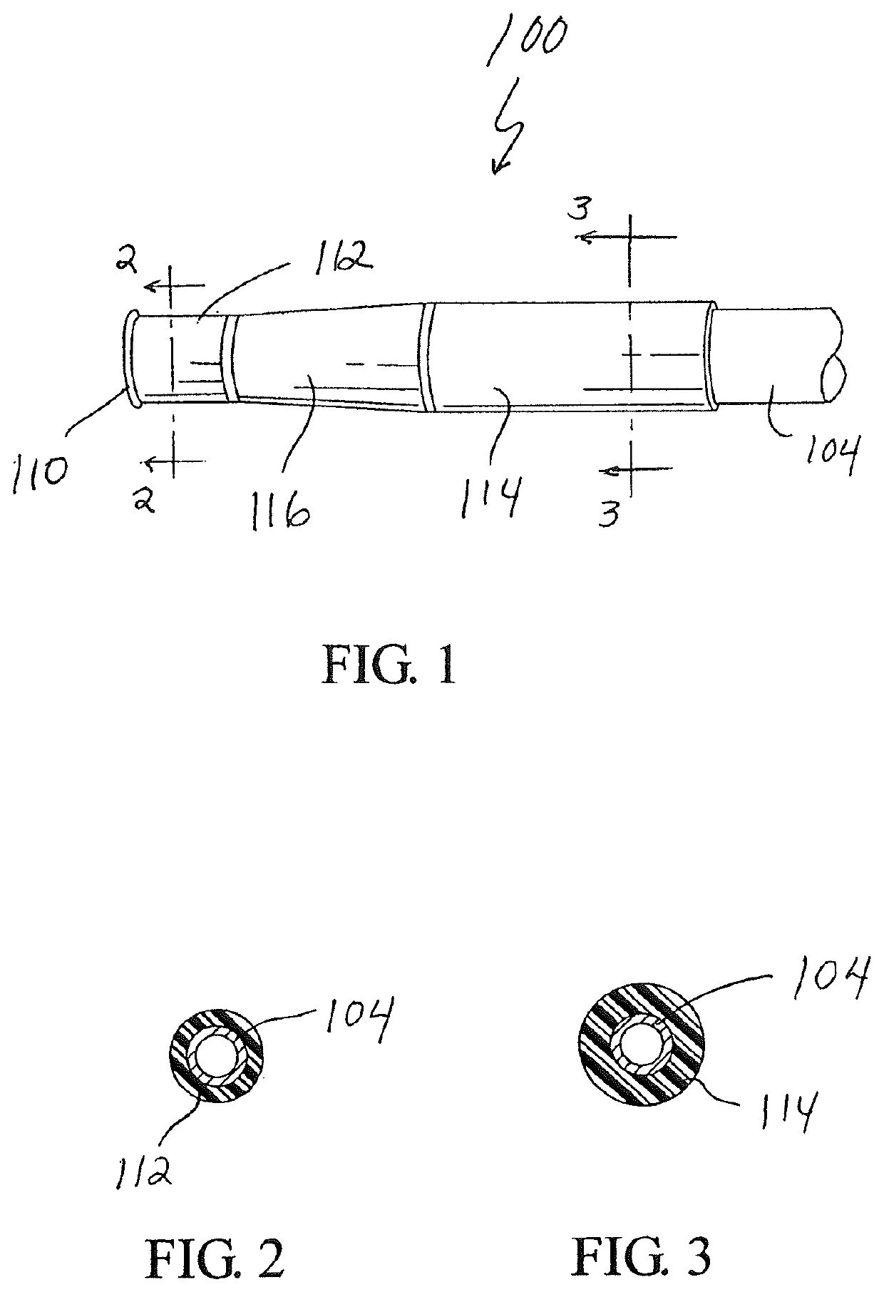
[0025]Referring to FIGS. 1 to 5, a full swing golf grip 100 in accordance with the present invention is shown attached to a golf club 102 on a shaft 104 at the opposite end of a club head 106. The grip 100 preferably is a unitary, single molded unit typically made of rubber or similar, generally flexible composite material. The grip 100 is generally cylindrical in shape and has a hollow interior. The grip 100 includes an opening 108 at the lower end to enable it to be placed over the golf club shaft 104 and a cap 110 at the top or butt end that covers the upper end of the shaft 104.

[0026]The grip 100 is formed in three separate, interconnected gripping sections, including an upper section 112, a lower section 114 and an intermediate or transitional section 116 between the upper section 112 and the lower section 114. The upper section 112 has a first non-tapered, constant outer diameter along the entire length of the upper section 112, as shown in FIG. 2. The lower section 114 has a ...


PUM


Abstract

A unitary golf grip for attachment to the handle of a golf club having three gripping sections including an upper section to accommodate the little finger of the golfer's upper hand; a tapered intermediate section to accommodate the remaining three fingers of the golfer's upper hand; and, a lower section to accommodate the fingers of the golfers lower hand.

Description

CROSS REFERENCE[0001]This is application is a continuation of U.S. patent application Ser. No. 14,285,701, filed May 23, 2014, which is a continuation-in-part of U.S. patent application Ser. No. 10 / 765,106, filed Jan. 28, 2004, which is a continuation of U.S. patent application Ser. No. 10 / 238,585, filed May 11, 2002, titled “Handle Configuration for a Putter Type Golf Club,” which claims the benefit of prior provisional application Ser. No. 60 / 344,376, filed Jan. 4, 2002, titled “Golf Putter Handle” and Ser. No. 60 / 359,724, filed Feb. 27, 2002, titled “Golf(Club) Putter Handle,” the specifications of which are each hereby incorporated by reference.BACKGROUND OF THE INVENTION[0002]Normally a golf club is gripped with both hands at the end of the golf club shaft on a grip portion formed at the upper end of the club. Historically the grip has been formed with a constant diameter or with a grip that tapers toward the club head from the butt end of the club having the larger grip diamet...

Claims


Application Information

Patent Timeline
Patent Type & Authority Applications(United States)
IPC IPC(8): A63B53/14A63B60/14A63B60/10A63B49/08
CPCA63B60/14A63B60/10A63B49/08A63B53/14
Inventor FERRIS, RICHARD D
Owner FERRIS RICHARD D
Why Eureka
Try Eureka