Mounting device for a support device

a technology for supporting devices and mounting devices, which is applied in the direction of vehicle maintenance, tractor-trailer combinations, vehicles, etc., can solve the problems of poor flexibility and large labor costs, and achieve the effect of convenient and cost-effective mounting and cost-effectiveness

Active Publication Date: 2020-07-23
SAF HOLLAND GMBH
View PDF7 Cites 3 Cited by
  • Summary
  • Abstract
  • Description
  • Claims
  • Application Information

AI Technical Summary

Benefits of technology

[0004]According to the invention, a mounting device for a support unit, in particular for commercial vehicles, comprises at least one supporting area, a first fixing area and a second fixing area, wherein the supporting area is designed to absorb the supporting forces, especially in the supporting direction, from the support unit or a support tube, wherein the first fixing area and the second fixing area are designed to fix the mounting device to a further element, especially a semi-trailer, wherein the first fixing area has at least one hole, wherein the second fixing area has at least one hole, and wherein the holes are designed to receive fixing means. The mounting device may, among other things, be part of a support unit, and in this embodiment the supporting area may be formed, inter alia, by the support tube itself or by a portion thereof, or by a surface on which the support tube can be fixed. The support tube in particular is the upper part of the support unit, which advantageously engages telescopically with the lower part of the support unit. The lower part of the support unit serves, among other things, for making contact with a bracing surface, such as the ground, in order to brace the further element. In an alternative embodiment, the mounting device may also be a separate component, which is arranged between the support unit and the further element. In this kind of mounting device, the supporting area is in particular the region of the mounting device on which the supporting device or the support tube is braced or arranged. Regardless of the configuration, the supporting area is therefore characterized in that it is adapted to absorb supporting forces from the support unit, the support tube, or other bracing elements that are acting in particular in the supporting direction, in order to brace the further element. Advisedly, the supporting area in order to accomplish its purpose can be arranged between the two fixing areas. In other words, the supporting area can thus separate the fixing areas from each other. The supporting direction is in particular that direction in which the support tube or the support unit primarily extends. In other words, the supporting direction may therefore in particular be the direction which is oriented opposite to the vector of gravity acceleration. The fixing areas of the mounting device serve for diverting the supporting forces absorbed by the supporting area from the mounting device directly or indirectly into the further element. The diverting may thus occur indirectly, for example by a mounting bracket, or directly by a direct contact of one or both fixing areas with a further element. The further element may be formed, for example, by a trailer, a semi-trailer, or their vehicle frames, or by a mounting bracket. The at least one hole in the first fixing area and the at least one hole in the second fixing area are round, especially at least for a portion, and serve for receiving fixing means such as screws or bolts, so that the mounting device can be secured directly or indirectly on a further element. In this way, the support unit is secured, especially in reversible (nondestructive) manner, detachably on the further element, so that the support unit can be mounted easily and cost effectively. Thanks to the flexibility of the connection, the mounting device is able to be subjected even to high dynamic forces. The holes pass through the mounting areas preferably entirely and are round at least for a portion, so that the holes can be oblong holes, among others. Preferably, however, the holes are circular round, so that they can be produced in an especially cost effective manner.

Problems solved by technology

This integrally bonded fixation, which is usually done by welding on, results in large labor expense and poor flexibility in the case of heavy loading.

Method used


Image

  • Mounting device for a support device
  • Mounting device for a support device
  • Mounting device for a support device

Examples


Embodiment Construction

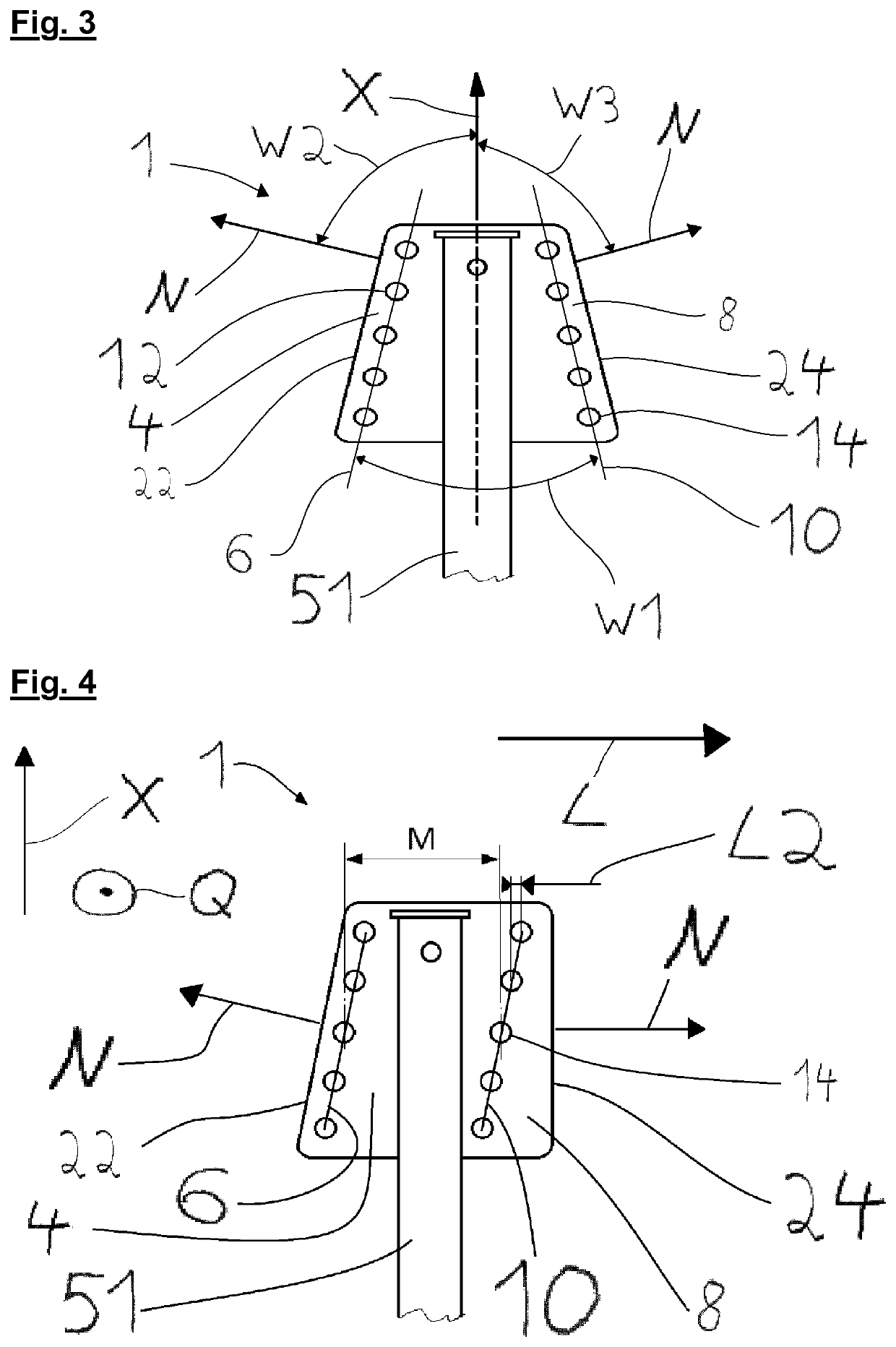
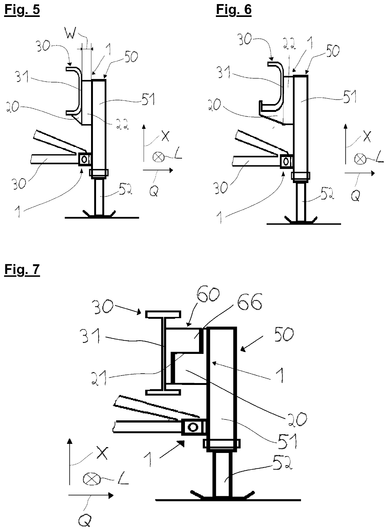
[0029]FIG. 1 shows in the upper region of the supporting device 50 a primary mounting device 1, comprising a first fixing area 4, a second fixing area 8 and a supporting area 2. The supporting area 2 serves to absorb forces, especially in the supporting direction X, from the support tube 51 of the supporting device 50. The supporting device 50 comprises, among other things, the support tube 51 and a lower part of the support unit 52, which is adapted to make contact with the ground. In the arrangement shown in FIG. 1, the supporting device 50 is secured by both a primary mounting device 1 (top) and a secondary mounting device 1 (bottom) on the further element 30. The primary mounting device 1 is spaced apart from the secondary mounting device1 in the positive supporting direction X. The primary mounting device 1 shown in FIG. 1 has four holes 12 in its first fixing area 4, forming a first hole series 6 with each other. The distally bordering surface of the first fixing area 22 borde...


PUM


Abstract

A mounting device for a support unit for commercial vehicles includes at least one supporting area, a first fixing area and a second fixing area, wherein the supporting area is configured to absorb the supporting forces in the supporting direction from the support unit or a support tube, wherein the first fixing area and the second fixing area are configured to fix the mounting device to a semi-trailer, wherein the first fixing area has at least one hole, wherein the second fixing area has at least one hole, and wherein the holes are configured to receive a fastener.

Description

BACKGROUND OF THE INVENTION[0001]The present invention relates to a mounting device for supporting devices, especially those of commercial vehicles, as well as a mounting bracket for a mounting device.[0002]Supporting devices or support jacks are known in the prior art. They serve for bracing and / or adjusting the height of trailers, semi-trailers or vehicles. The supporting devices known in the prior art usually comprise to this end an outer and an inner support tube, which can be telescopically fitted together. For the mounting on a trailer, semi-trailer, or vehicle, mounting devices are provided on the supporting devices, which are arranged with integral bonding on a corresponding surface of the trailer, especially in the case of heavily loaded supporting devices. This integrally bonded fixation, which is usually done by welding on, results in large labor expense and poor flexibility in the case of heavy loading.[0003]The problem which the invention proposes to solve is to provide...

Claims


Application Information

Patent Timeline
Patent Type & Authority Applications(United States)
IPC IPC(8): B60S9/04B60S9/22
CPCB60S9/04B62D53/06B60S9/22B60S9/02
Inventor WALLMEIER, STEFANWEBER, ELMAR
Owner SAF HOLLAND GMBH
Why Eureka
Try Eureka