Eureka AIR delivers breakthrough ideas for toughest innovation challenges, trusted by R&D personnel around the world.

Method to produce a veneer element and a veneer element

a technology of veneer elements and elements, applied in the field of methods to produce veneer elements, can solve the problems of poor aesthetic appeal to consumers, incomplete homogeneous structure and appearance of veneer elements, and defects in veneer elements, and achieve the effect of improving the visual impression of the veneer layer after pressing

Active Publication Date: 2020-07-09
VÄLINGE INNOVATION AB
View PDF0 Cites 27 Cited by
  • Summary
  • Abstract
  • Description
  • Claims
  • Application Information

AI Technical Summary

Benefits of technology

The present invention aims to improve the wear resistance of a veneer surface. It does this by using a binder that prevents particles from the sub-layer from permeating through microscopic openings in the veneer layer. This binder also helps to bring pigments through the veneer layer without colouring it. The technical effect of this invention is a veneer surface that is more durable and visually appealing.

Problems solved by technology

Veneer is made of wood and is not fully homogeneous in the structure and appearance.
For example, the veneer may comprise a crack that occurred during cutting the veneer.
Or the veneer may comprise a hole, such as a knot hole, thus being a defect naturally occurring the veneer.
Most often such veneers would be considered by the manufacture to be of low quality and go to waste or used for other applications.
Such an appearance in not aesthetically appealing to the consumer.
The veneer element may comprise defects and dense portions.
Such defects may be naturally occurring or may be formed during cutting the veneers, especially if cutting thin veneers as having a thickness of less than 1 mm.
Said defects may form such coloured portions of the veneer layer.
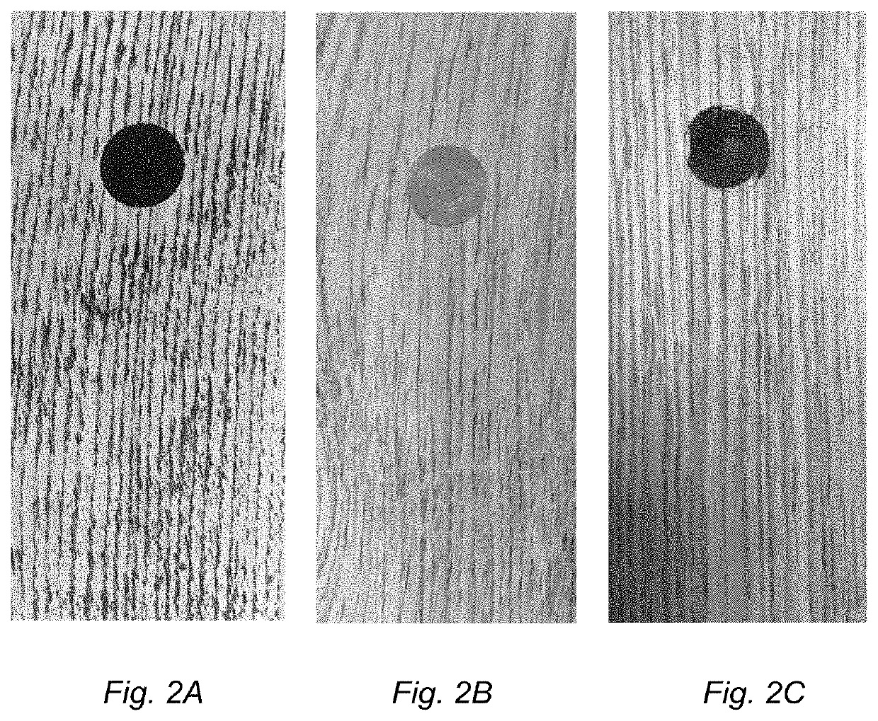
However, defects such as crack, cavity, hole and / or knot hole are coloured by the coloured particles in the sub-layer after pressing.
It is desirable to colour defects with a dark colour, while it is undesirable to colour the solid portions of the veneer element with a dark colour.
When using conventional pigments in the sub-layer, it has been shown that pigment particles permeate through microscopic opening in porous portions of the dense portions, thereby colouring also the dense portions of the veneer layer, which is undesirable.
The coloured filler particles used are too dense for the binder to bring them through the veneer layer and thereby permeate.
However, pigments conventionally used easily follow the binder during pressing and permeates through dense portions of the veneer layer, thereby colouring also dense portions.
Consequently, coloured filler particles are not conventionally used in the meaning of pigment in the industry.
The veneer layer may comprise defects and dense portions.
Such defects may be naturally occurring or may be formed during cutting the veneers, especially if cutting thin veneers as having a thickness of less than 1 mm.
Said defects may form such coloured portions of the veneer layer.
However, defects such as crack, cavity, hole and / or knot hole are coloured by the coloured particles in the sub-layer after pressing.
It is desirable to colour defects with a dark colour, while it is undesirable to colour the solid portions of the veneer element with a dark colour.
When using conventional pigments in the sub-layer, it has been shown that pigment particles permeate through microscopic opening in the dense portions, thereby colouring also the dense portions of the veneer layer, which is undesirable.
The coloured filler particles used are too dense for the binder to bring them through the veneer layer and thereby permeate.
However, pigments conventionally used easily follow the binder during pressing and permeates through dense portions of the veneer layer, thereby colouring also dense portions.
Consequently, coloured filler particles are not conventionally used in the meaning of pigment in the industry.

Method used


Image

  • Method to produce a veneer element and a veneer element
  • Method to produce a veneer element and a veneer element
  • Method to produce a veneer element and a veneer element

Examples


example 1

Testing of Various Filler Materials

[0172]Several dark coloured filler materials, listed as additives 1 to 11 (Table 1), were selected because of their different properties, material classes and varying shape and size. However, the size was still within the desired particle range for this application of at least 0.1 μm in diameter.

TABLE 1Coloured filler particles used.ParticleNo.Additive nameMaterial classcharacteristic1Petrit TMetallic / ceramic blendPowder2Petrit T-SMetallic / ceramic blendGranules3MT-1Metallic with highPowdercarbon content4Brown pelletsOrganicGrinded to fibrouspowder5Coffee (coarse)OrganicGrinded coarsely topowder6Coffee (Fine)OrganicGrinded finely topowder7Distaloy AEMetalWater atomized ironpowder alloy8Arbocel SpheresOrganicSpherical granulate(black)9Vitacel AF-401OrganicFibrous powder(apple fibre)10Cocoa fibreOrganicFibrous powder11BarkOrganicPowder12Heat treatedOrganicFibrous powderSonae 30013Dyed Sonae 300OrganicFibrous powder

[0173]Additive with number 13 in Tabl...

example 2

[0183]Following was performed in order to prove that fine particles of a size less than 0.1 μm, such as free pigments in the formulation are easily carried by the melamine formaldehyde resin melt flow when applying heat and pressure. On the contrary, coarse particles of the size at least 0.1 μm in diameter e.g. dark coloured filler particles like a burned Sonae 300 fibre or a grinded brown pellet would have the binder separate from the solid loading under when melting under heat and pressure. Pucks were formed from different powders, comprising a melamine-formaldehyde resin, wood fibre, and either pigments or dark fillers. These pucks were then cured under heat and pressure, where the binder would, in case of separation from the solid phase create a transparent rim of the pressed puck, whereas this rim would be opaque if the coloured solid loading was carried by the melt phase.

TABLE 6Colouring agents used in Example 2.SampleColouring additive1Printex 60 (pigment)2MT-1 (colour filler...

example 3

[0186]The scope of this experiment was to evaluate how particle size, characteristic and density affected the permeation results from Example 1. Sieving analysis of different additives was conducted according to the parameters defined in Table 7. The additives tested are presented in Table 8 and the sieving results are visualized on FIG. 4. FIG. 4 illustrates the results of the sieving analysis of the samples, wherein it is apparent that the majority of the coloured filler particles are of at least 0.1 μm or more in diameter, preferably between 0.1 μm and 300 μm in diameter.

[0187]That while fine coffee particles and Petrit T shown an acceptable degree of permeation (Table 8), an increase in particle size to the coarse Coffee and Pertite T-S further decreased or eliminated a degree of permeation into the dense portions of the veneer layer.

TABLE 7Sieving parameters.Sample mass:50gSieve time:20minAmplitude:1.8mmNo. of Balls:5

TABLE 8Overview of additives evaluated in the experiment.Samp...


PUM

PropertyMeasurementUnit
Lengthaaaaaaaaaa
Fractionaaaaaaaaaa
Diameteraaaaaaaaaa

Abstract

A method to produce a veneer element, including defects and dense portions. The method includes providing a substrate, providing a sub-layer, including a binder and coloured filler particles, applying the sub-layer on a first surface of the substrate, applying a veneer layer on the sub-layer, and applying pressure, preferably heat and pressure, to the veneer layer and / or the substrate, thereby forming a veneer element wherein, after pressing, the sub-layer is visible through a defect of the veneer element such as crack, cavity, hole and / or knot of the veneer layer. Also, a veneer element.

Description

CROSS REFERENCE TO RELATED APPLICATIONS[0001]The present application claims the benefit of Swedish Application No. 1950017-2, filed on Jan. 9, 2019, and the benefit of Swedish Application No. 1950668-2, filed on Jun. 5, 2019. The entire contents of each of Swedish Application No. 1950017-2 and Swedish Application No. 1950668-2 are hereby incorporated herein by reference in their entirety.TECHNICAL FIELD[0002]Embodiments of the present invention relate to a method to produce a veneer element and such a veneer element.TECHNICAL BACKGROUND[0003]Veneer layers may be used as a construction material, for example in the form of plywood. Plywood is formed of several veneer layers being glued together, for example with urea formaldehyde or phenol formaldehyde. The veneer layers are glued to each other in low pressure method in a temperature of about 140° C. and at a pressure about 10 bar. After pressing, the glue is present as a thin layer between the veneer layers. The veneer layers retain ...

Claims


Application Information

Patent Timeline
IPC IPC(8): B32B21/14B32B21/02B27N3/06E04F15/10E04F15/04E04F13/10
CPCB32B2471/00B32B2264/105B32B2264/0214B27N3/06E04F15/045B32B21/14B32B2264/107B32B21/02E04F15/107E04F13/10E04F15/102E04F15/043E04F13/16B27N7/005B32B13/08B32B9/06B32B2255/28B32B2255/26B32B2307/732B32B2607/00B32B29/005B32B21/10B32B2307/72B32B2260/028B32B27/10B32B2255/08B32B13/02B32B21/06B32B21/042B32B9/042B32B5/022B32B9/005B32B2260/046B32B21/08B32B13/10B32B2479/00B32B2307/402B32B2250/02B32B2250/03B32B7/12B32B37/24
Inventor HEDLUND, ANETTENILSSON, SOFIA
Owner VÄLINGE INNOVATION AB
Why Eureka
Eureka Blog
Learn More