
Optical Line Terminal And Optical Fiber Access System With Increased Capacity

a technology of optical fiber access system and optical line terminal, which is applied in the direction of multiplex communication, electrical apparatus, and wavelength-division multiplex systems, can solve the problems of reducing the capacity of current pon technology, so as to increase the transmission capacity of optical access system and achieve the effect of increasing the capacity of pon system and enhancing the transmission capacity

Active Publication Date: 2020-07-02
DANMARKS TEKNISKE UNIV
View PDF0 Cites 4 Cited by
  • Summary
  • Abstract
  • Description
  • Claims
  • Application Information

AI Technical Summary

Benefits of technology

The patent is about a new technology called time lens that can be used in optical communication networks to increase data rates and save energy. It can be applied to PON systems to allow for point-to-multipoint and multi-multipoint communication. The technology also allows for the generation of multiple WDM channels from a single TDM signal source, resulting in higher dispersion tolerance and better power budget for long-reach PON systems. Additionally, the technology provides flexibility in terms of wavelength allocation and transmission performance, making it more efficient than conventional WDM PON and TDM-PON systems. Overall, the technology disclosed in the patent can increase capacity and flexibility in optical communication networks.

Problems solved by technology

A beam splitter cannot provide any switching or buffering capabilities and does not use any power supply.
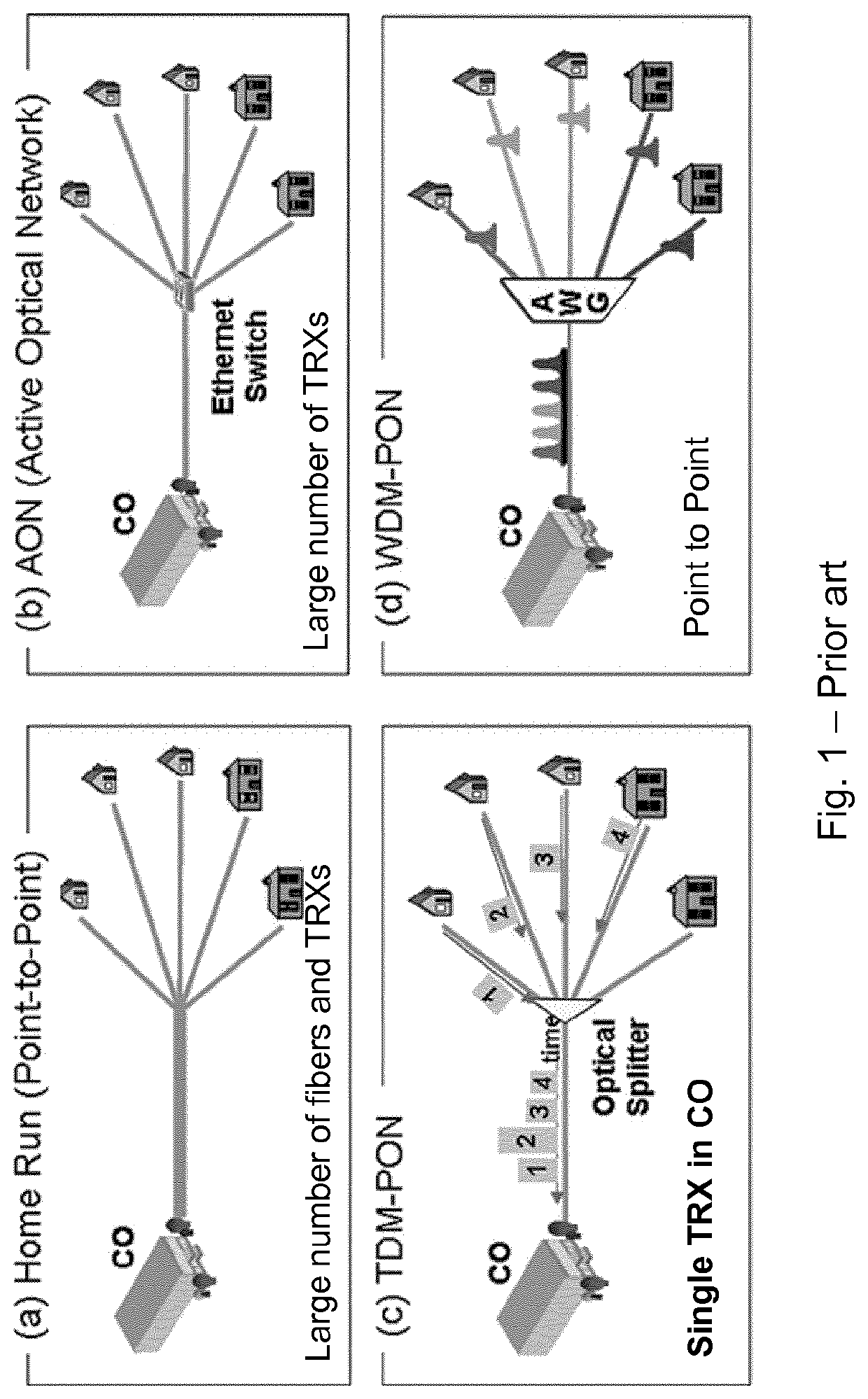
Even though optical fibers have large bandwidth, current PON technology will run out of capacity in 4-5 years due to:Growing number of subscribersGrowing number of connected devices per subscriberIncreasing bandwidth demands per device or application
Increasing the serial bitrate beyond 10 Gb / s of PON systems is difficult due to lower dispersion tolerance and the lower signal to noise ratio (SNR).
The key challenge for TWDM-PON is to realize its optical network unit (ONU) at low cost, the cost is predicted to be more than 20 times that of a standard GPON (Gigabit-PON) ONU [1].
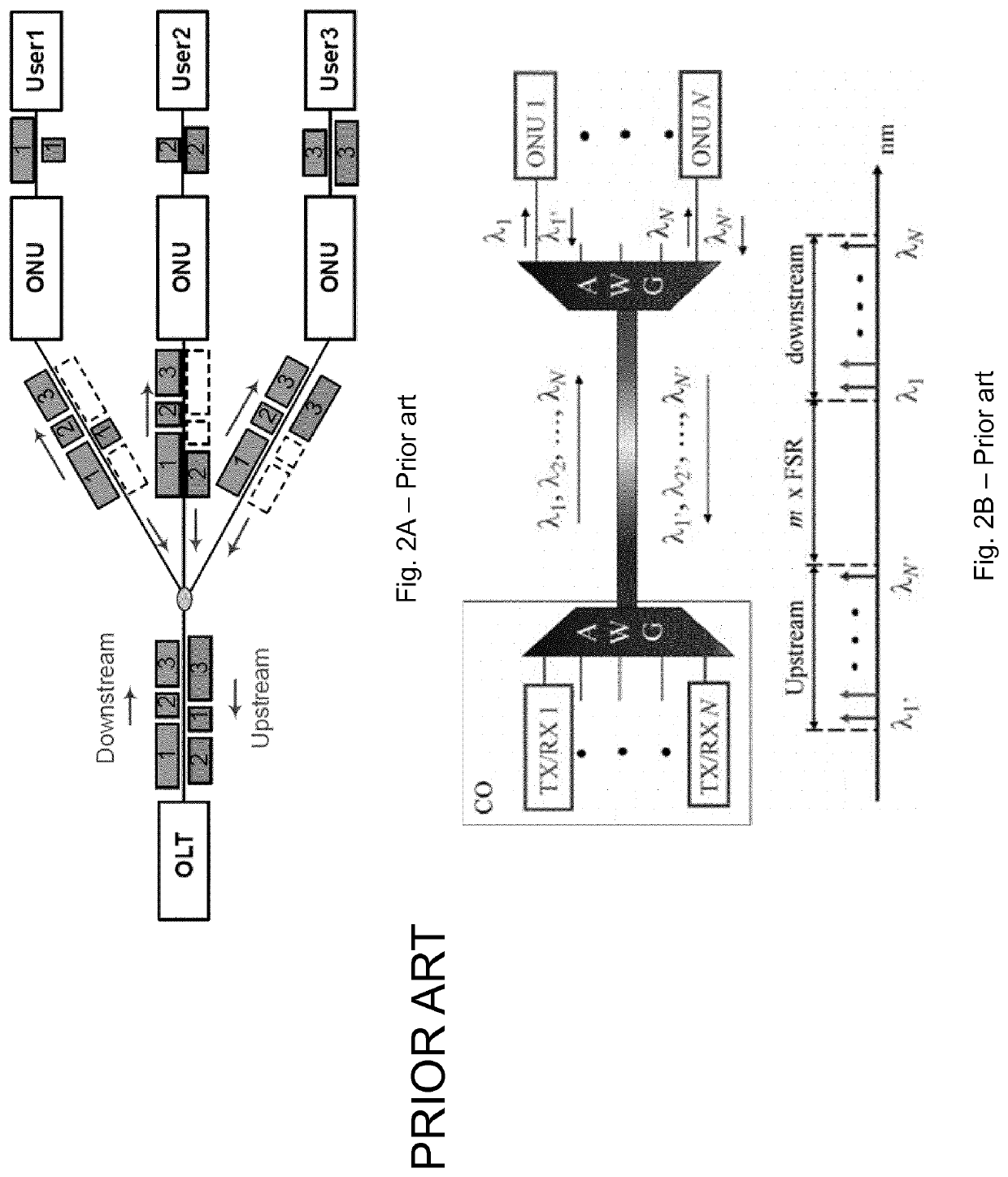
A major disadvantage of P2P WDM-PON is the large port count, transmitters and terminations at the central office (CO) requiring more CO space and operational cost.

Method used


Image

  • Optical Line Terminal And Optical Fiber Access System With Increased Capacity
  • Optical Line Terminal And Optical Fiber Access System With Increased Capacity
  • Optical Line Terminal And Optical Fiber Access System With Increased Capacity

Examples


example 1

[0098]The presently disclosed time-lens PON approach has been demonstrated experimentally. A 40-Gbit / s PON downstream transmission over 150-km 40-split unamplified SMF-plant has been obtained with a single-carrier OOK transmitter and low-cost 10-GHz APD-based receiver, achieving a power budget of 51.5 dB (35.5 dB / ch.) for a BER=3×10⁻⁶. Meanwhile, the same system achieves 128 Gb / s PON over 100 km 64 split unamplified Fiber-Plant using optical TDM technique, showing flexibility and scalability of the presently disclosed scheme in terms of wavelength control and system capacity.

[0099]Principle and Experimental Setup

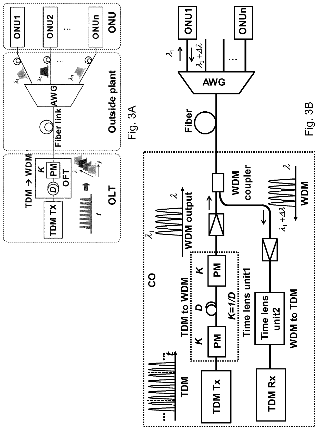
[0100]One example of the presently disclosed OLT structure / PON architecture is shown in FIG. 3A and this setup is used here in example 1. In the optical line terminal (OLT), a single carrier TDM transmitter generates a high-speed TDM signal, which is then converted to a number of low-speed WDM channels using a time-lens based OFT signal processor, which comprises a dispersiv...

example 2

[0107]In this example the scalability of the presently disclosed solution is investigated and 128×2 Gb / s WDM PON downstream transmission over a 100-km unamplified SMF-plant is demonstrated using a 200 m highly nonlinear fiber (HNLF, for example from OFS). Although all 128 generated WDM channels achieve BERs below the 10−3 forward error-correction (FEC) limit after transmission, a bandwidth limitation of the HNLF is observed, which will limit the scalability of the proposed scheme. To overcome this issue the use of AlGaAs-on-insulator (AlGaAsOI) nonlinear waveguides [6,7] for implementing the time lens is investigated. The same 128×2 Gb / s WDM PON system using an AlGaAs device is demonstrated, which achieves similar performance as HNLF, but without showing indications of having reached a bandwidth limitation.

[0108]Principle and Experimental Setup

[0109]The principle is the same as shown in FIG. 3a. In the OLT, a single TDM transmitter generates a high-speed TDM signal, which is then co...


PUM


Abstract

The present disclosure relates to an optical fiber access system based on passive optical networks. In particular the present disclosure relates to a PON system with increased capacity and a method for increasing the capacity in a PON system. One embodiment relates to an optical line terminal for a passive optical network, comprising at least one transmitter for generating a time division multiplexed (TDM) downstream optical data signal, a first time lens optical signal processor configured to convert the downstream TDM signal to a downstream WDM signal for distribution to a plurality of users, and at least one receiver for receiving and processing an upstream signal from said users.

Description

[0001]The present disclosure relates to an optical line terminal that can be used in an optical fiber access system based on passive optical networks. The present disclosure further relates to a PON system with increased capacity and a method for increasing the capacity in a PON system.BACKGROUND OF INVENTION[0002]The incessant rise in data consumption by both fixed and mobile broadband subscribers drives continuous industry innovation to meet this challenge. Optical fiber access systems based on passive optical networks (PON) are currently being deployed on a mass market scale by numerous network operators. PON systems are often referred to as the “last mile” between an internet service provider and an individual user, i.e. PON systems are typically used to provide fiber to the end consumer, normally using a point-to-multipoint architecture, wherein unpowered fiber optic splitters can be used to enable a single optical fiber to serve multiple end-points. The end-points are often in...

Claims


Application Information

Patent Timeline
Patent Type & Authority Applications(United States)
IPC IPC(8): H04J14/02
CPCH04J14/0209H04J14/0223H04J14/0246H04J14/0267
Inventor GUAN, PENGYUOXENLØWE, LEIF KATSUO
Owner DANMARKS TEKNISKE UNIV
Learn More