Wireless communication apparatus and antenna device

Active Publication Date: 2020-06-25
UNIVERSITY OF ELECTRO-COMMUNICATIONS
View PDF0 Cites 1 Cited by
  • Summary
  • Abstract
  • Description
  • Claims
  • Application Information

AI Technical Summary

Benefits of technology

The patent text describes a device related to a certain technology. The device has certain technical effects that are not specified in the text. These effects may be explained in other parts of the patent text or in other parts of the technology.

Problems solved by technology

Unfortunately, these wireless systems require many valuable frequency resources.
Unfortunately, mixed signals are mathematically separated in MIMO, and thus complicated signal processing is required.
Since a plurality of antennas is operated in cooperation, there also arises a problem that system configuration is complicated.
In contrast, in a microwave, transmission and reception methods of an eigenmode and methods of transmitting a focused beam are greatly different from those in the optical communication, and thus the OAM wave is not easily achieved.

Method used


Image

  • Wireless communication apparatus and antenna device
  • Wireless communication apparatus and antenna device
  • Wireless communication apparatus and antenna device

Examples


first embodiment

1. First Embodiment

[0062]A first embodiment of the invention will be described below with reference to FIGS. 1 to 24.

[1-1. Configuration of Entire System]

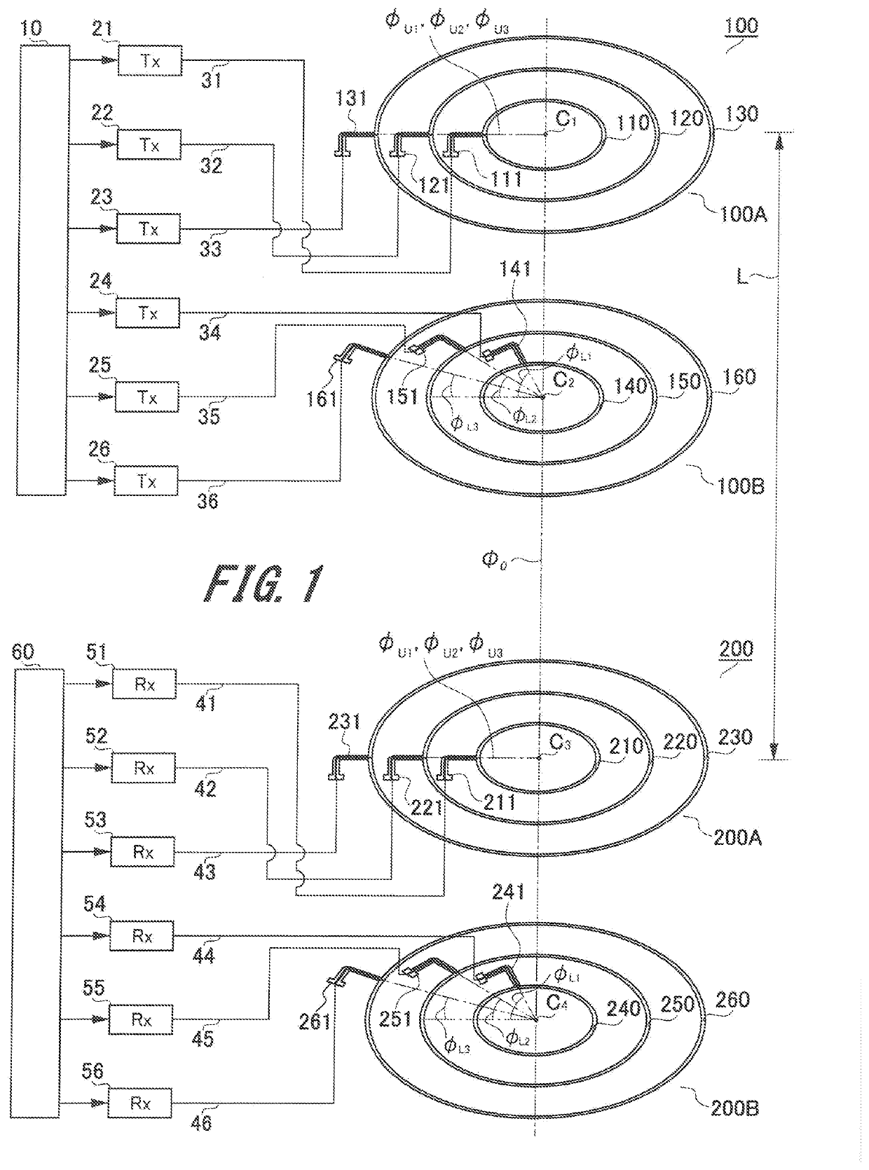
[0063]FIG. 1 illustrates a configuration example of an entire wireless communication apparatus of the first embodiment.

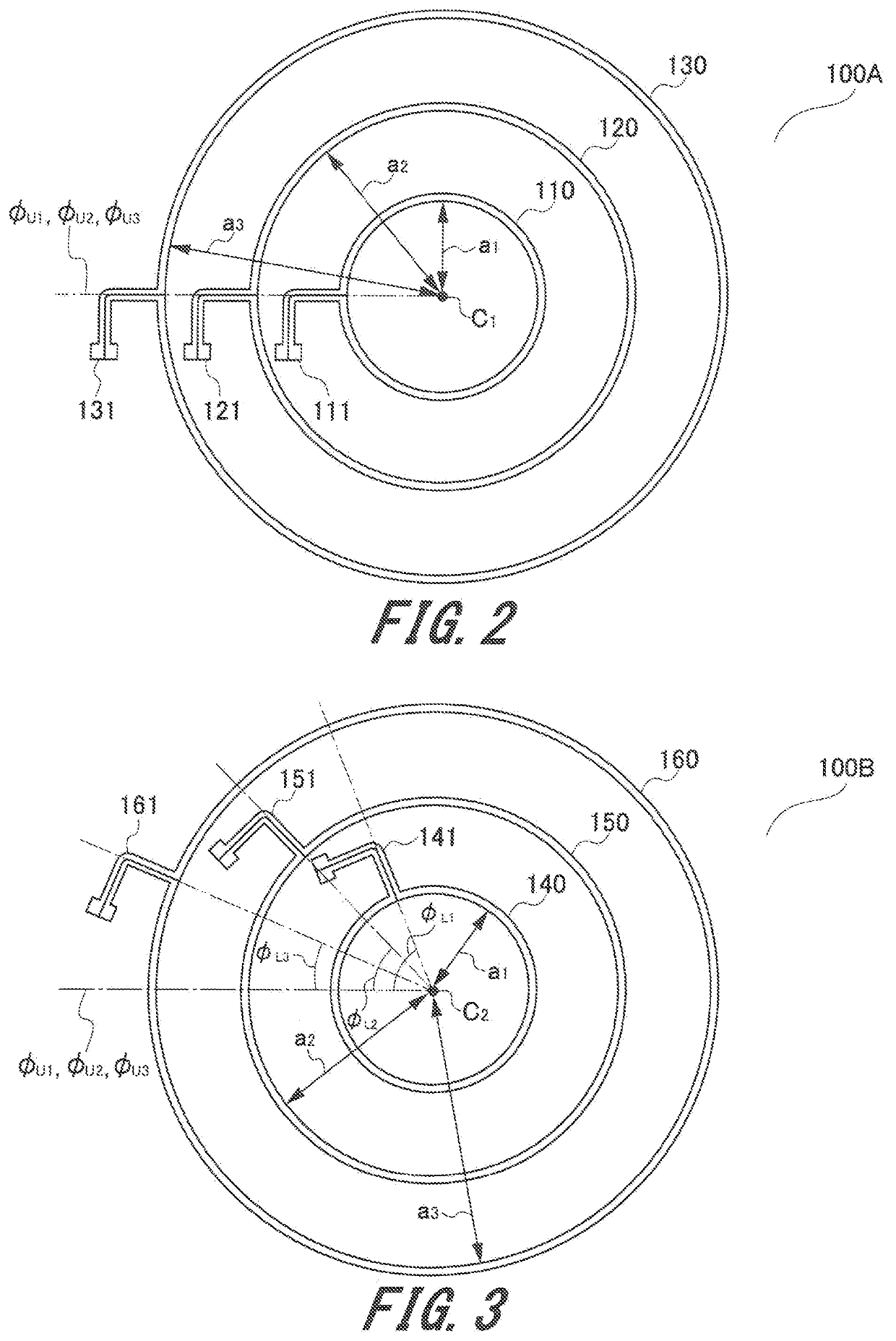
[0064]The wireless communication apparatus of the first embodiment performs wireless communication from a transmitting antenna 100 to a receiving antenna 200 at a relatively short distance. The transmitting antenna 100 and the receiving antenna 200 have the same configuration, and each antenna includes a plurality of (here, six) circular loop antenna elements 110 to 160 and 210 to 260. FIGS. 2 and 3 illustrate the configurations of the upper and lower surfaces of the transmitting antenna 100. The receiving antenna 200 also has the same shape as the transmitting antenna 100.

[0065]That is, the transmitting antenna 100 includes six circular loop antenna elements 110, 120, 130, 140, 150, and 160. The six circular loop ...

second embodiment

2. Second Embodiment

[0150]A second embodiment of the invention will now be described with reference to FIGS. 25 to 38.

[0151]In FIGS. 25 to 38 for describing the second embodiment, the same signs are attached to the same members as those in the first embodiment described with reference to FIGS. 1 to 24, and the detailed description thereof will be omitted.

[2-1. Configuration of Antenna Device]

[0152]FIG. 25 illustrates the configurations of a transmitting antenna 100′ and a receiving antenna 200′ of the embodiment and a transmission system and a reception system connected thereto.

[0153]FIGS. 26 and 27 are plan views of a first circular loop antenna group 100A′ (FIG. 26) of the transmitting antenna 100′ and a second circular loop antenna group 100B′ (FIG. 27) on the lower surface side.

[0154]In the second embodiment, the first circular loop antenna group 100A′ on the upper surface side and the second circular loop antenna group 100B′ on the lower surface side are provided as the transmi...


PUM


Abstract

Circular loop antenna elements of each of a transmitting antenna and a receiving antenna have different perimeters of approximately integral multiples of a wavelength determined from a wireless communication frequency. The transmitting antenna and the receiving antenna include first circular loop antenna groups concentrically disposed on the same plane and second circular loop antenna groups including circular loop antenna elements of the same perimeter as that of a plurality of circular loop antenna elements of the first circular loop antenna group. An angular position of a terminal for connecting power supply units to circular loop antenna elements having the same perimeter is set to an angular position rotated by (2l+1)π / 2mi (where l is any integer, and mi is a value of m1 to mN that are approximately integral multiples of a wavelength) in the first and second circular loop antenna groups.

Description

TECHNICAL FIELD[0001]The present invention relates to a wireless communication apparatus and an antenna device, and more particularly to a wireless communication apparatus capable of simultaneously and wirelessly transmitting data on a plurality of systems by using the same frequency band and an antenna device used for the wireless communication apparatus.BACKGROUND ART[0002]In recent years, rich content on the Internet and the spread of ultrahigh-speed networks over optical lines and wireless networks to end users have caused rapid progress to the advanced information society that enables information provision tailored to individual needs of “anytime, anywhere, and with anyone” and furthermore “only now, only here, and only you”. Big data collection by communication without involving humans over sensor networks is also progressing in parallel. Various systems, such as mobile phones, worldwide interoperability for microwave access (WiMAX), wireless local area networks (LAN), Bluetoo...

Claims


Application Information

Patent Timeline
IPC IPC(8): H01Q21/24H01Q21/06H01Q7/00H01Q25/00
CPCH01Q25/00H01Q21/24H01Q21/06H01Q7/00H01Q21/28
Inventor SAITOU, AKIRAOTSUKA, HIROTOHONJO, KAZUHIKOISHIKAWA, RYO
Owner UNIVERSITY OF ELECTRO-COMMUNICATIONS
Why Eureka
Try Eureka