Rearview device and vehicle with such rearview device
a rearview device and rearview technology, applied in the field of external rearview devices, can solve the problems of not always being produced from parts, and it is difficult to guide light from such light emitting diodes to another location, and achieve the effect of reducing the aerodynamic resistance of the vehicle and being easy to moun
- Summary
- Abstract
- Description
- Claims
- Application Information
AI Technical Summary
Benefits of technology
Problems solved by technology
Method used
Image
Examples
first embodiment
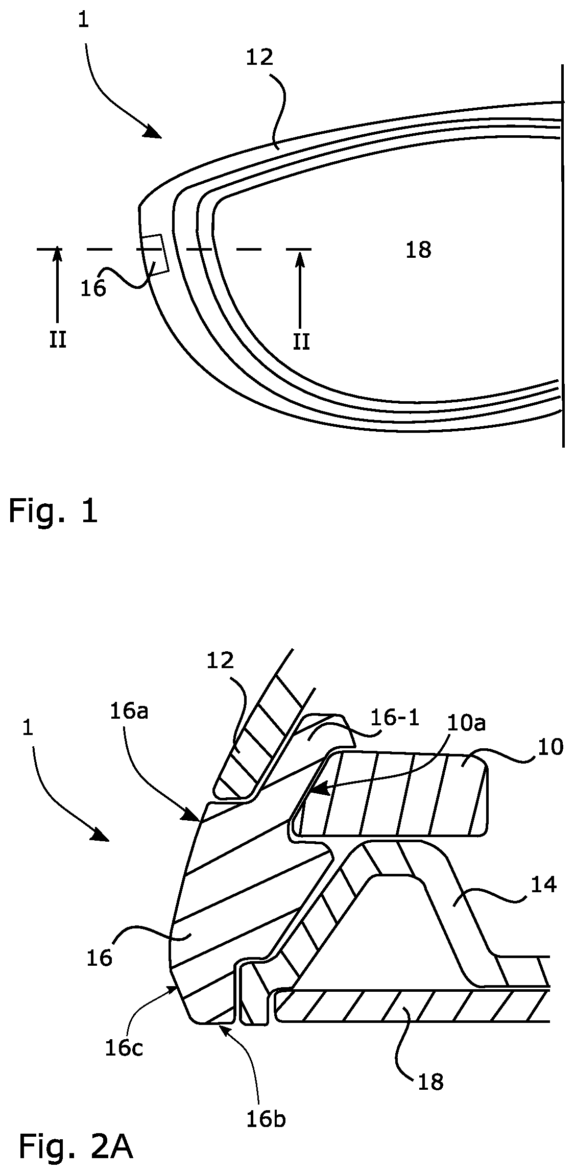
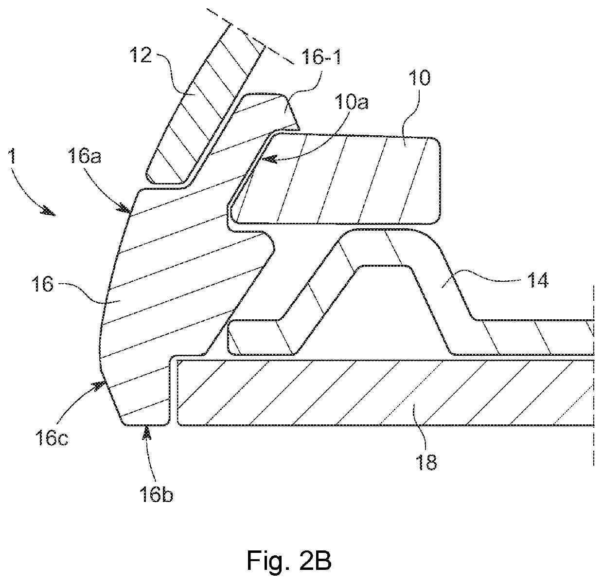
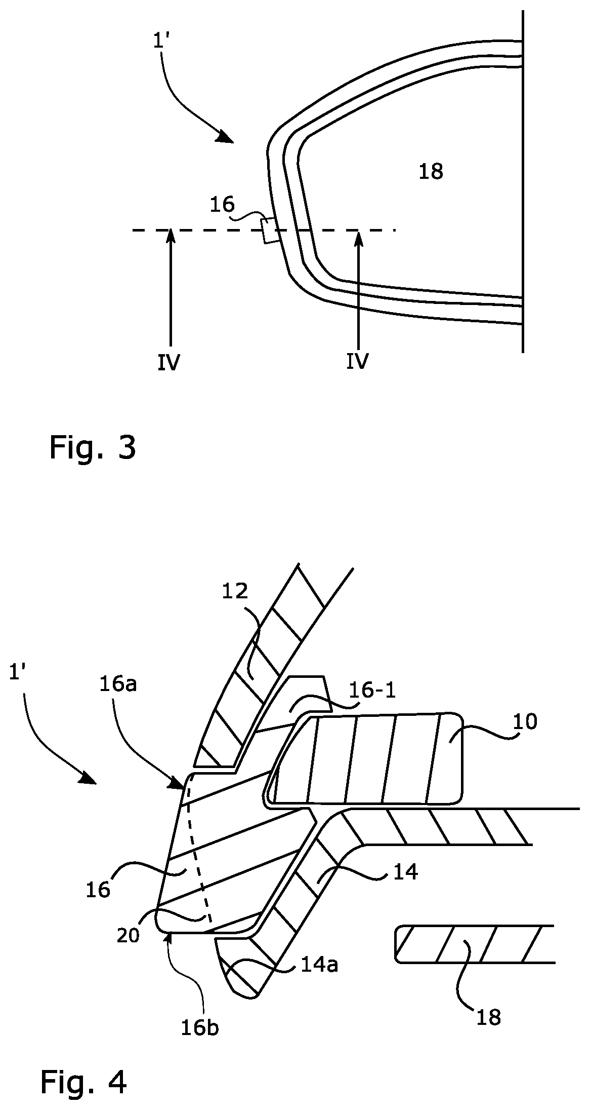
[0075]FIG. 1 depicts a rearview mirror indicated at 1, being a rearview device according to a The rearview mirror 1 comprises a light producing device 10, arranged within a housing being made up of a hollow shell or casing a wall 12 of which is shown in the sectional view of FIG. 2A or FIG. 2B. In the example of FIG. 2A, part of the housing is also a bezel 14, in a known manner, wherein a transparent lens-like element 16 is arranged between the wall 12 and the bezel 14, to complement these two parts when forming the overall housing, preferably in manner for the housing to be tight. For instance, the transparent element 16 can be clamped between the wall 12 and the bezel 14. The transparent element 16 can be formed out of glass, or produced by moulding transparent plastic material, and in all examples herein is fully transparent, but could as well be only portion-wise transparent as long as its function explained hereinafter is fulfilled.
[0076]In the example of FIG. 1 with the cross...
second embodiment
[0082]In both rearview mirrors 1 and 1′, the first as well as the second embodiment, the light producing device 10 is provided as a compact entity or unit and, thus, in form of a module as depicted in FIG. 5. At the heart thereof is a printed circuit board 22 that bears at least one light emitting device (LED) 24. The printed circuit board 22 is held in a lower half 26 of the light producing device 10 that is covered by an entirely transparent upper half (cover) 28. Ports 30 enable the supply of electrical energy to the printed circuit board 22. The printed circuit board 22 includes all elements necessary for controlling the LED 24, like a control unit and impedance matching elements (not shown). The LED 24 is suited for being intermittently operated (flashing) under such control, in order to provide a side turn indicator unit of the rearview mirror 1, 1′. Instead of using separable halves 26, 28, the printed circuit board 22 can be integral with the remainder of the body, such as c...
fourth embodiment
[0083]FIGS. 6 and 9 show alternative light producing devices 40 to be used with a third and fourth embodiment of a rearview device 101′, 101″. Each one of said alternative light producing devices 40 is more or less bullet shaped. In both alternatives the light producing devices 40 are provided with at least one optical fibre 48 for guiding light emitted from a not shown LED to a pin 44 that terminates in a dome-shaped end portion 42. Fixing means 46 e.g. in form of clamping arms are optional.
[0084]FIG. 7 depicts the third embodiment incorporating a fixed mirror solution. The housing of the rearviewdevice 101′ according to FIG. 7 makes usage of the elements 12, 14 already described with respect to FIG. 2. But the transparent element 16 of the third embodiment differs from the one shown in FIG. 2, by providing a cavity for accommodating the dome-shaped end portion 42 of the light producing device 40.
PUM
 Abstract
Description
Claims
Application Information
 - R&D
- Intellectual Property
- Life Sciences
- Materials
- Tech Scout
- Unparalleled Data Quality
- Higher Quality Content
- 60% Fewer Hallucinations
Browse by: Latest US Patents, China's latest patents, Technical Efficacy Thesaurus, Application Domain, Technology Topic, Popular Technical Reports.
© 2025 PatSnap. All rights reserved.Legal|Privacy policy|Modern Slavery Act Transparency Statement|Sitemap|About US| Contact US: help@patsnap.com


