
Tire tread

a technology of tire treads and tread bands, which is applied in the direction of tyre tread bands/patterns, vehicle components, transportation and packaging, etc., can solve the problems of increasing the need for pneumatic tires to reduce rolling resistance, noise performance during running, ride comfort, and other performance characteristics, and achieves the effect of increasing the cornering stiffness of the tire tread

Inactive Publication Date: 2020-06-18
THE GOODYEAR TIRE & RUBBER CO
View PDF0 Cites 0 Cited by
  • Summary
  • Abstract
  • Description
  • Claims
  • Application Information

AI Technical Summary

Benefits of technology

This patent describes a method to make a tire tread that has more cornering stiffness. This is accomplished by creating alternating rows of grooves in the shoulder of the tire tread. The first grooves are located closer to a main groove on one side of the shoulder, while the second grooves are located farther out. There are also double blind lateral sipes, which are wider in the middle between each pair of grooves. These sipes are important to maintaining the stiffness of the tire tread. The result is a tire that can better corner and has improved performance on the road.

Problems solved by technology

In view of resource saving and global environmental issues, pneumatic tires are increasingly being required to decrease the rolling resistance.
However, if the volume of the tread rubber and / or sidewall rubber is decreased, the noise performance during running, ride comfort, and other performance characteristics tend to deteriorate.
If a tread rubber having a low heat generation property is used, the braking performance and steering stability tend to deteriorate.
Thus, the reduction of rolling resistance has conventionally had an adverse effect on still other performance characteristics such as steering stability and braking performance.

Method used


Image

  • Tire tread
  • Tire tread
  • Tire tread

Examples


Embodiment Construction

OF THE PRESENT INVENTION

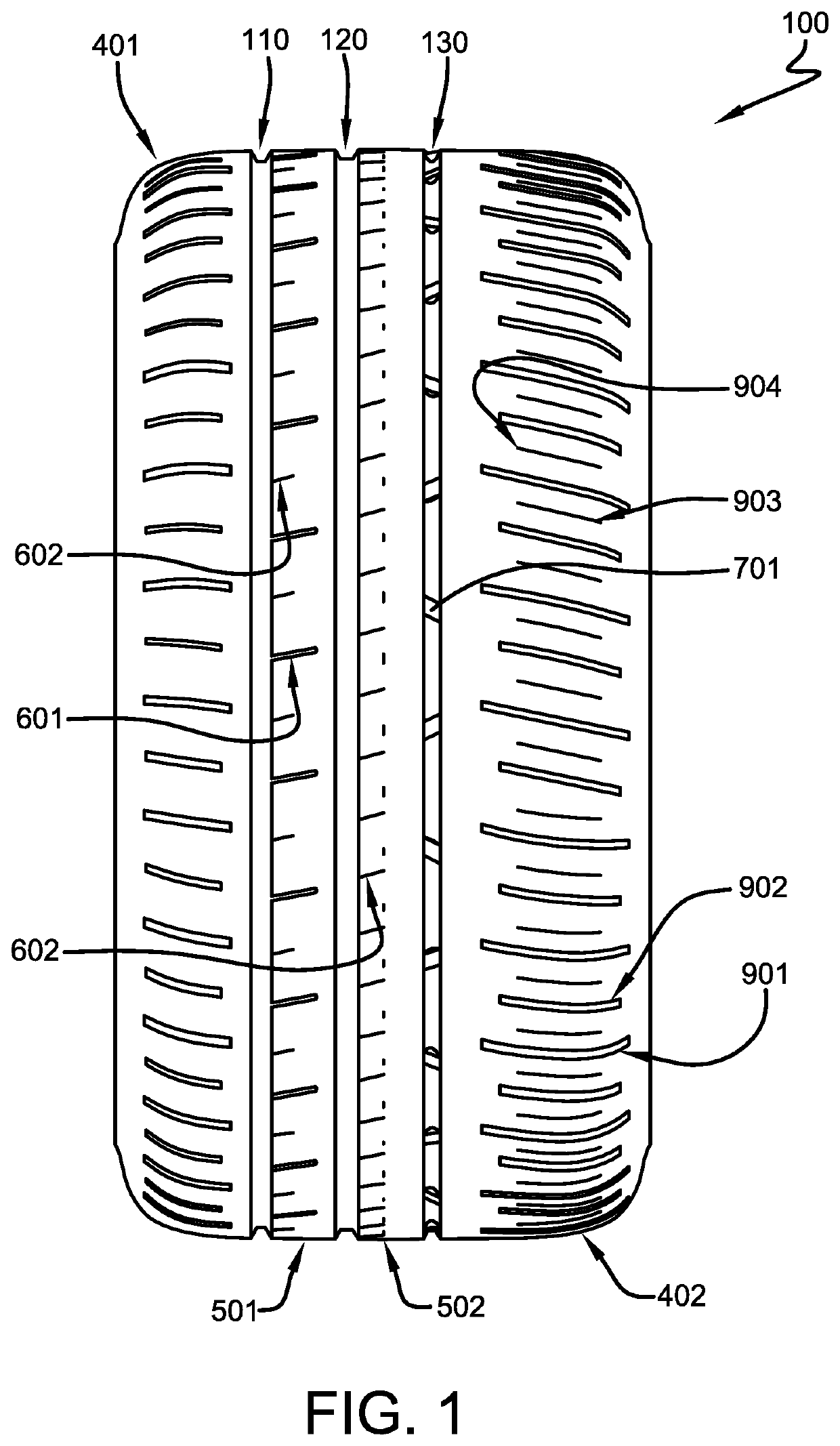
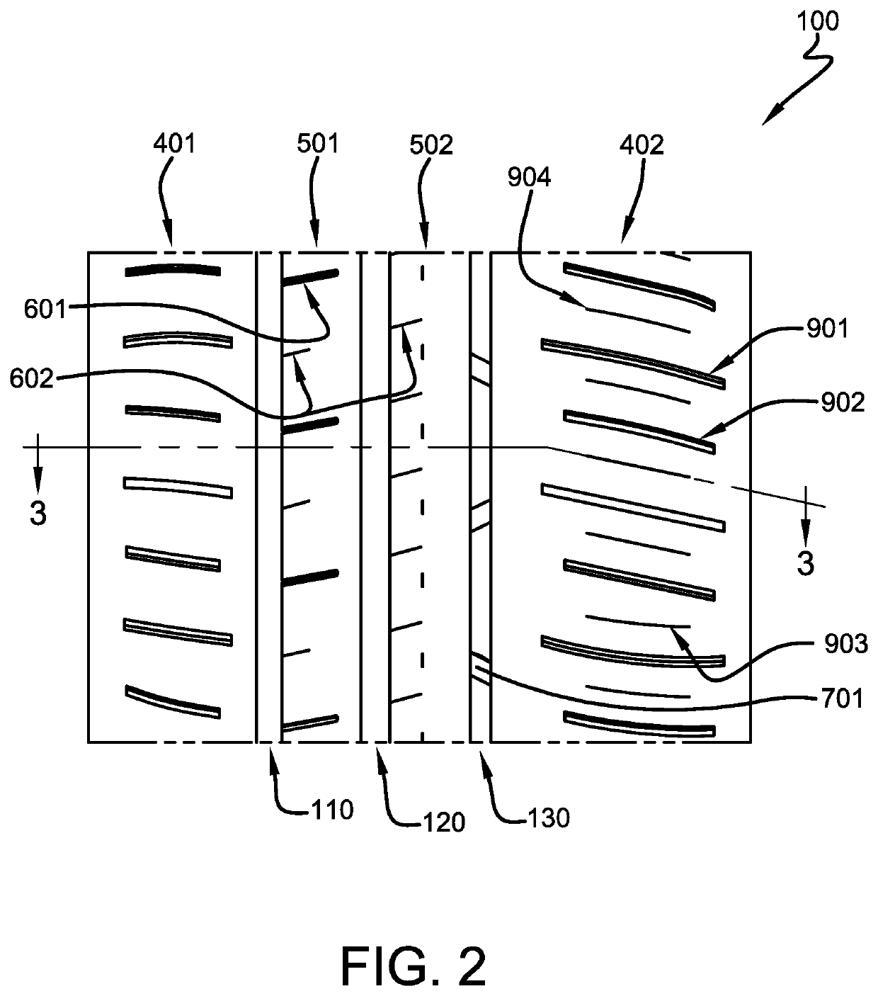
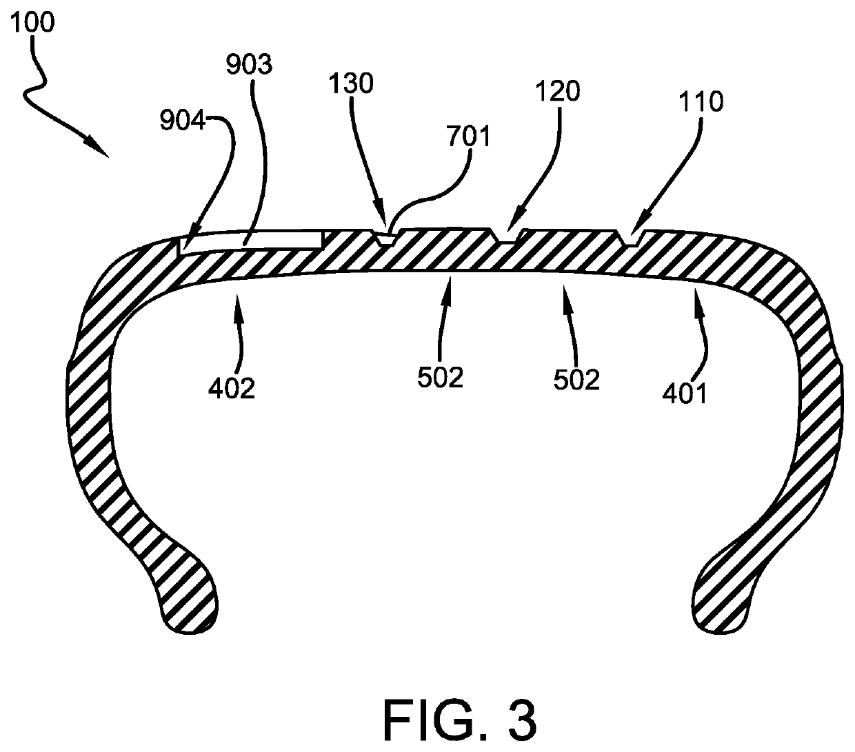
[0051]As shown in FIGS. 1 through 3, a tread 100 for use with the present invention may have a first circumferential main groove 110, a second circumferential main groove 120, and a third circumferential main groove 130 defining a first shoulder rib 401, a first intermediate rib 501, a second intermediate rib 502, and a second shoulder rib 402. Each rib 401, 402, 501, 502 may have a variety of transverse grooves 601 and sipes 602 suitable for tire treads. One of the circumferential main grooves 110, 120, 130 (the third groove 130 in FIGS. 1 and 2) may have several connecting bridges 701 spaced circumferentially within the main groove. Similar tread structures are disclosed in U.S. Ser. No. 15 / 713,730, filed on Sep. 25, 2018 by the current applicant, herein incorporated by reference in its entirety. As many as thirty or more connecting bridges 701 may be included in a single tread 100. As an example, the connecting bridges 701 may connect the axially outer sec...


PUM


Abstract

A tread for a tire includes a first circumferential main groove, a second circumferential main groove, and a third circumferential main groove. The first, second, and third circumferential main grooves together define a first shoulder rib, a first intermediate rib, a second intermediate rib, and a second shoulder rib. The second shoulder rib has a plurality of first linear, lateral grooves circumferentially alternating with a plurality of second linear, lateral grooves and a plurality of double blind lateral sipes disposed circumferentially midway between each adjacent first lateral groove and second lateral groove. The first and second lateral gooves extend both axially and circumferentially toward the third circumferential main groove. The first lateral grooves terminate nearer the third circumferential main groove than the second lateral grooves.

Description

FIELD OF THE INVENTION[0001]The present invention relates generally stiffening tread patterns for improving steering performance.BACKGROUND OF THE INVENTION[0002]In view of resource saving and global environmental issues, pneumatic tires are increasingly being required to decrease the rolling resistance. The rolling resistance may be decreased by decreasing the energy loss in various rubber components of the tread of a tire. For that purpose, conventionally employed are elastomeric materials having as low heat generation properties as the rubber of the tread. Also, tread and sidewall volume may be decreased. However, if the volume of the tread rubber and / or sidewall rubber is decreased, the noise performance during running, ride comfort, and other performance characteristics tend to deteriorate. If a tread rubber having a low heat generation property is used, the braking performance and steering stability tend to deteriorate. Thus, the reduction of rolling resistance has conventiona...

Claims


Application Information

Patent Timeline
Patent Type & Authority Applications(United States)
IPC IPC(8): B60C11/03B60C11/12
CPCB60C11/1259B60C2011/0358B60C2011/0341B60C2011/0334B60C11/1272B60C11/0304B60C11/1236B60C2011/0381B60C11/032B60C2011/039B60C2011/1209B60C2011/1254B60C2011/0365B60C11/1307
Inventor SANGALLI, ROBERTO GIOVANNIBODE, MATTHIASFEHL, HELMUT WOLFGANG
Owner THE GOODYEAR TIRE & RUBBER CO
Learn More