
Directional solidification cooling furnace and cooling process using such a furnace

a solidification cooling furnace and cooling process technology, applied in the field of casting parts cooling, can solve the problems of parts with distortion and torsion of thermomechanical stresses, final parts with weak zones, etc., and achieve the effects of limiting thermomechanical stresses and plastic deformation in metal, regulating more accurately, and limiting thermomechanical stresses and plastic deformation

Active Publication Date: 2020-06-11
SN DETUDE & DE CONSTR DE MOTEURS DAVIATION S N E C M A +1
View PDF0 Cites 2 Cited by
  • Summary
  • Abstract
  • Description
  • Claims
  • Application Information

AI Technical Summary

Benefits of technology

The patent text describes a method for controlling the temperature of a casting by using two heat shields, one stationary and one carried by the mold support. This helps to prevent the temperature of the casting from being affected by neighboring zones, resulting in better control over cooling and reduced temperature gradients. This method also reduces the risk of defects and recrystallized grains in the casting.

Problems solved by technology

Nevertheless, during solidification and cooling of the metal, large temperature gradients may exist between the various portions of the mold and the metal, thereby giving rise to distortions and to thermomechanical stresses in the part.
Nevertheless, since the parts that are presently being produced are becoming ever more complex (new alloys, hollow or solid turbine blades and / or ever finer wall thicknesses), the thermomechanical stresses that arise may lead to re-crystallized grains and cracks forming during solidification and cooling of those blades, thereby leading to zones of weakness in the final part.

Method used


Image

  • Directional solidification cooling furnace and cooling process using such a furnace
  • Directional solidification cooling furnace and cooling process using such a furnace
  • Directional solidification cooling furnace and cooling process using such a furnace

Examples


Embodiment Construction

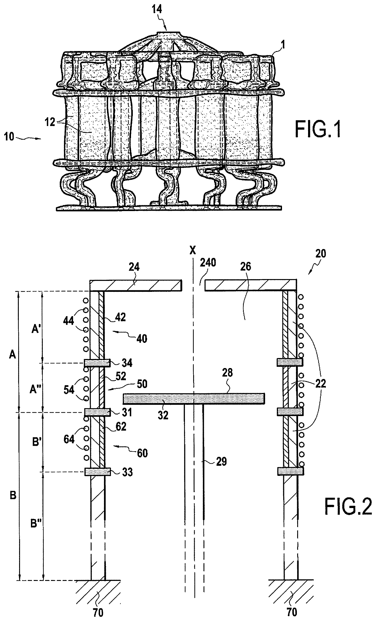
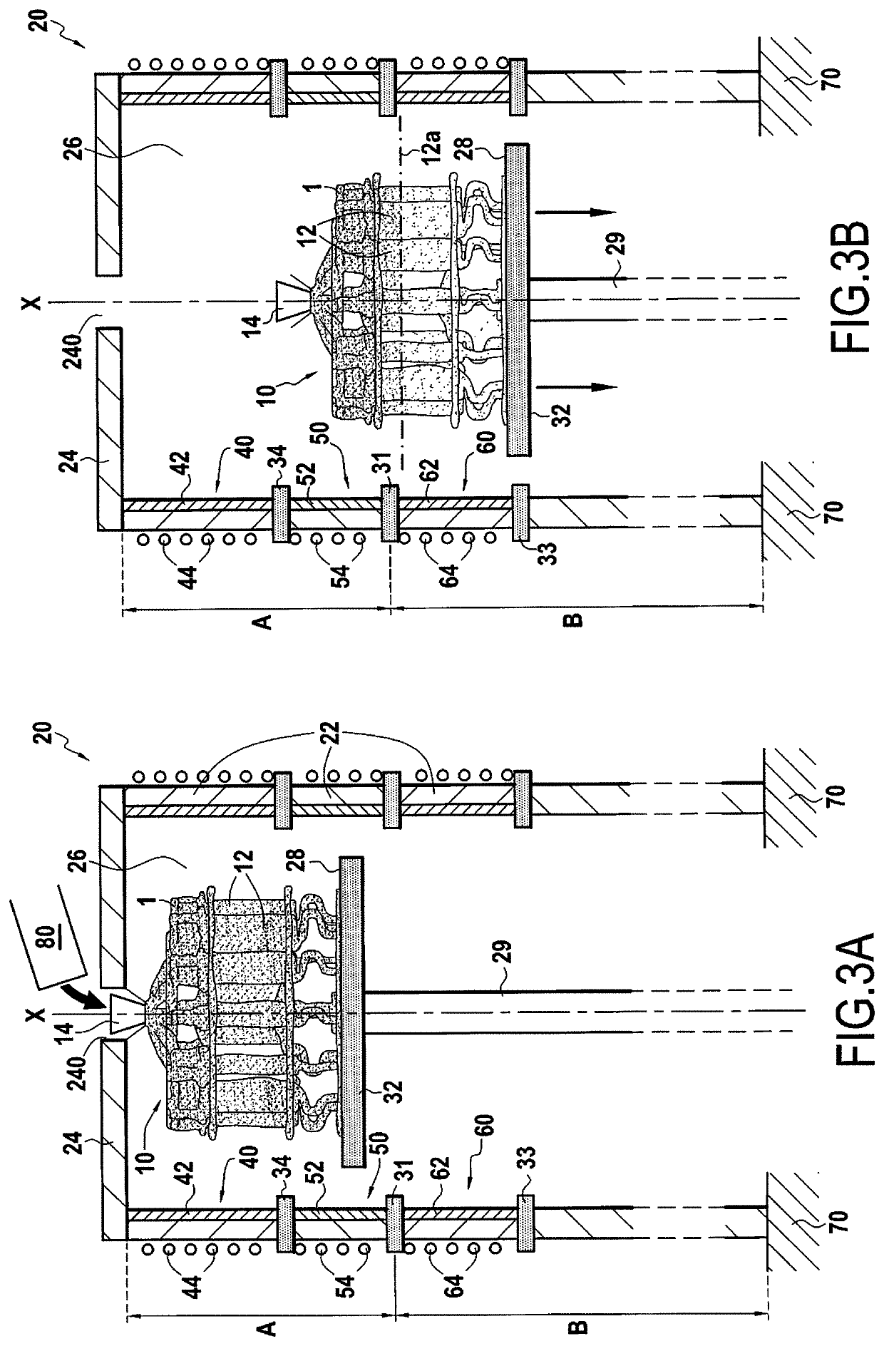
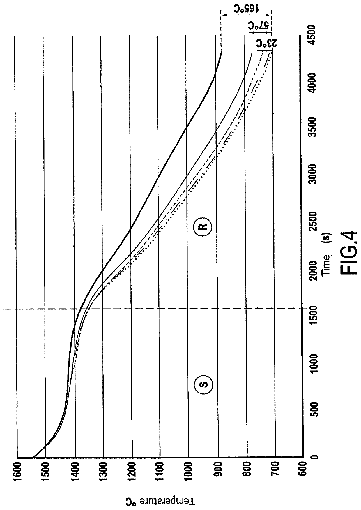
[0058]An example furnace 20 of the present disclosure and an example cooling method by directional solidification for use with blades made by casting are described below with reference to FIGS. 1 to 5.

[0059]Blades are fabricated by a casting method. A first step in this casting method consists in fabricating a model of the blades and in grouping together a plurality of models so as to form a cluster enabling a mold to be fabricated, as described in the following step.

[0060]In a second step, a shell mold 1 is fabricated from the wax cluster.

[0061]The last operation of the second step consists in eliminating the wax of the cluster model from the shell mold 1. Wax is eliminated by raising the shell mold 1 to a temperature higher than the melting temperature of the wax.

[0062]In a third step, a cluster 10 of blades 12 (FIG. 1) is formed in the shell mold 1 by casting molten metal into the shell mold 1. Molten metal is cast into the shell mold 1 from the top portion of the mold, referred ...


PUM

PropertyMeasurementUnit
diameteraaaaaaaaaa
temperatureaaaaaaaaaa

Abstract

A directional solidification cooling furnace for metal casting part comprises: a cylindrical internal enclosure having a vertical central axis and a mold support arranged in the internal enclosure; the internal enclosure comprising a casting zone and a cooling zone, the casting zone and the cooling zone being superposed one on the other; the casting and cooling zones being thermally insulated from each other when the mold support is arranged in the casting zone by means of a heat shield that is stationary and by means of a second heat shield that is carried by the mold support; the casting zone including at least a first heating device, and the cooling zone including a second heating device.

Description

FIELD OF THE INVENTION[0001]The present invention relates to the field of cooling metal parts made by casting, and more particularly to a directional solidification cooling furnace for metal casting part, and also to a method of directional solidification cooling of a metal casting part by making use of such a furnace.STATE OF THE PRIOR ART[0002]So-called “lost wax” or “investment” casting methods are particularly suitable for producing metal parts of complex shapes. Thus, investment casting is used in particular for producing turbine engine blades.[0003]In investment casting, the first step is to make a model out of a material having a melting temperature that is comparatively low, such as for example a wax or a resin, with a mold then subsequently being overmolded onto the model. After the mold has consolidated, the model material is evacuated from inside the mold. Molten metal is then cast into the mold in order to fill the cavity formed by evacuating the model from the mold. Onc...

Claims


Application Information

Patent Timeline
Patent Type & Authority Applications(United States)
IPC IPC(8): B22D27/04
CPCB22D27/045
Inventor NIANE, NGADIA TAHAFARGEAS, SERGE ALAINBOUKERMA, SAIDTENNE, SERGEMARTIN, GILLES
Owner SN DETUDE & DE CONSTR DE MOTEURS DAVIATION S N E C M A
Learn More