Tilting duct compound helicopter

a compound helicopter and duct technology, applied in the field of compound helicopters, can solve the problems of limited range, high energy consumption, and rapid fuel consumption, and achieve the effects of reducing power consumption, enhancing the flight characteristics of the rotorcraft, and facilitating horizontal fligh

Active Publication Date: 2020-05-28
TEXTRON INNOVATIONS
View PDF0 Cites 11 Cited by
  • Summary
  • Abstract
  • Description
  • Claims
  • Application Information

AI Technical Summary

Benefits of technology

The patent is about a new rotorcraft technology that combines the benefits of traditional helicopters and VTOL aircraft. It includes a main rotor and multiple articulating thrusters that provide vertical lift for takeoff and landing, and then switch to horizontal flight. The main rotor continues to provide vertical lift while in an unpowered autorotation mode, reducing power consumption and enhancing flight characteristics. The aircraft can also use a conventional edge-wise rotor and ducted fans to achieve vertical takeoff and sustained hover. The thrusters provide anti-torque and are aligned with the flight path for transition to cruise flight. The main rotor can provide energy for safe landing in the event of system failures. The technical effect of this technology is a more efficient and versatile rotorcraft that can save power and safely land in the event of failure.

Problems solved by technology

Conventional helicopters and Vertical Take-Off and Landing (VTOL) aircraft suffer from similar disadvantages, such as heavy energy sources, rapid fuel consumption, and limited range due to the rapid fuel consumption.
Because VTOL aircraft have thrusters capable of providing for both vertical lift and horizontal flight, these aircraft do not incorporate a traditional main rotor to generate vertical lift, since the added weight would further degrade aircraft performance.
Since VTOL aircraft lack a traditional main rotor, they can experience catastrophic consequences in emergency situations should their thrusters fail.
Perhaps the largest issue with any aircraft is weight management.
The implementation of additional components for redundant functionality typically comes with the penalty of reducing aircraft performance.
The powering step of the method can occur when the thrusters fail to receive energy from a primary energy source.

Method used


Image

  • Tilting duct compound helicopter
  • Tilting duct compound helicopter
  • Tilting duct compound helicopter

Examples


Embodiment Construction

[0014]The preferred version of the inventions presented in the following written description and the various features and advantageous details thereof are explained more fully with reference to the non-limiting examples included in the accompanying drawings and as detailed in the description which follows. Descriptions of well-known components are omitted so as to not unnecessarily obscure the principle features of the invention as described herein. The examples used in the following description are intended to facilitate an understanding of the ways in which the invention can be practiced and to further enable those skilled in the art to practice the invention. Accordingly, these examples should not be construed as limiting the scope of the claimed invention.

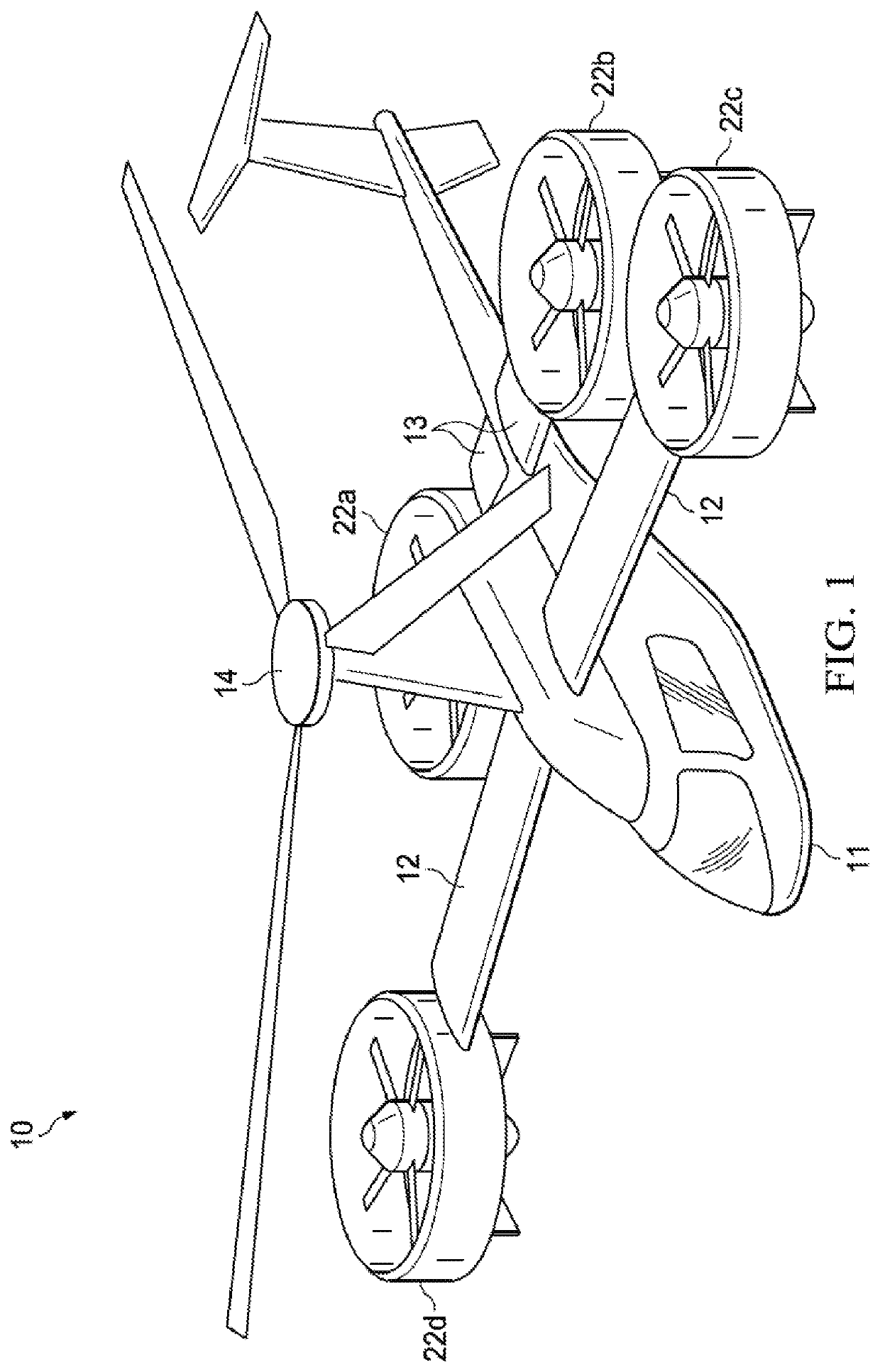
[0015]FIG. 1 is a perspective view of a compound rotorcraft, designated generally as 10, in accordance with an embodiment of the present disclosure. The compound rotorcraft 10 can include an airframe structure. The airframe str...


PUM


Abstract

A rotorcraft that utilizes both a main compound rotor and a plurality of tiltrotors is disclosed. The main rotor and the thrusters can provide vertical lift for vertical take-off and landing of the rotorcraft. The thrusters of the rotorcraft can articulate to a horizontal position to facilitate horizontal flight. The main rotor of the rotorcraft can continue to provide vertical lift for the rotorcraft in horizontal flight, as well as operate in an autorotation mode. In the event of a failure of the main power source of the rotorcraft, the main rotor in autorotation mode can safety land the rotorcraft. In the autorotation mode, the main rotor can create electrical energy that is stored in a battery and can be used to power the plurality of thrusters. The rotorcraft can also be configured in an anti-torque mode, where the thrusters cancel out the torque of the main rotor.

Description

BACKGROUND1. Field of the Invention[0001]The present invention is generally related to compound helicopters, and more specifically to compound helicopters incorporating articulating thrusters.2. Background of the Invention and Description of Related Art[0002]Conventional helicopters and Vertical Take-Off and Landing (VTOL) aircraft suffer from similar disadvantages, such as heavy energy sources, rapid fuel consumption, and limited range due to the rapid fuel consumption. Helicopters provide lift and forward flight using a main rotor. VTOL aircraft utilize a plurality of thrusters to provide lift and forward flight. Because VTOL aircraft have thrusters capable of providing for both vertical lift and horizontal flight, these aircraft do not incorporate a traditional main rotor to generate vertical lift, since the added weight would further degrade aircraft performance. Since VTOL aircraft lack a traditional main rotor, they can experience catastrophic consequences in emergency situati...

Claims


Application Information

Patent Timeline
Patent Type & Authority Applications(United States)
IPC IPC(8): B64C29/00B64D27/24B64C11/00B64C11/46
CPCB64C29/0033B64C11/46B64C11/001B64D27/24B64C27/28B64C27/02B64C27/52B64C29/00B64C27/20Y02T50/40B64D27/026
Inventor ROBERTSON, DANIELGRONINGA, KIRKLOUIS, MATTHEW
Owner TEXTRON INNOVATIONS
Why Eureka
Try Eureka