Parameter setting device, system, and parameter setting method

a parameter setting and system technology, applied in the field of parameter setting devices and system parameters, can solve the problems of unnecessarily longening the machining cycle time disadvantageously, shortening the life of the machine tool disadvantageously, and affecting the actual weight of the object on the table,

Inactive Publication Date: 2020-05-21
FANUC LTD
View PDF0 Cites 2 Cited by
  • Summary
  • Abstract
  • Description
  • Claims
  • Application Information

AI Technical Summary

Benefits of technology

[0004]When parameters relating to the table speed are manually set as described in Japanese Laid-Open Patent Publication No. 08-314531, there is a fear that the parameters might be set without considering the weight of the objects placed on the table, possibly resulting in parameter values inappropriate for the actual weight of the objects on the table. Performing machining operation with parameter settings corresponding to a heavier weight than the weight of the objects on the table may unnecessarily lengthen machining cycle time disadvantageously. On the other hand, performing machining operation with parameter settings corresponding to a lighter weight than the weight of the objects on the table may damage the machine tool, deteriorate machining accuracy to the workpiece, and shorten the life of the machine tool disadvantageously.

Problems solved by technology

When parameters relating to the table speed are manually set as described in Japanese Laid-Open Patent Publication No. 08-314531, there is a fear that the parameters might be set without considering the weight of the objects placed on the table, possibly resulting in parameter values inappropriate for the actual weight of the objects on the table.
Performing machining operation with parameter settings corresponding to a heavier weight than the weight of the objects on the table may unnecessarily lengthen machining cycle time disadvantageously.
On the other hand, performing machining operation with parameter settings corresponding to a lighter weight than the weight of the objects on the table may damage the machine tool, deteriorate machining accuracy to the workpiece, and shorten the life of the machine tool disadvantageously.

Method used


Image

  • Parameter setting device, system, and parameter setting method
  • Parameter setting device, system, and parameter setting method
  • Parameter setting device, system, and parameter setting method

Examples


embodiment

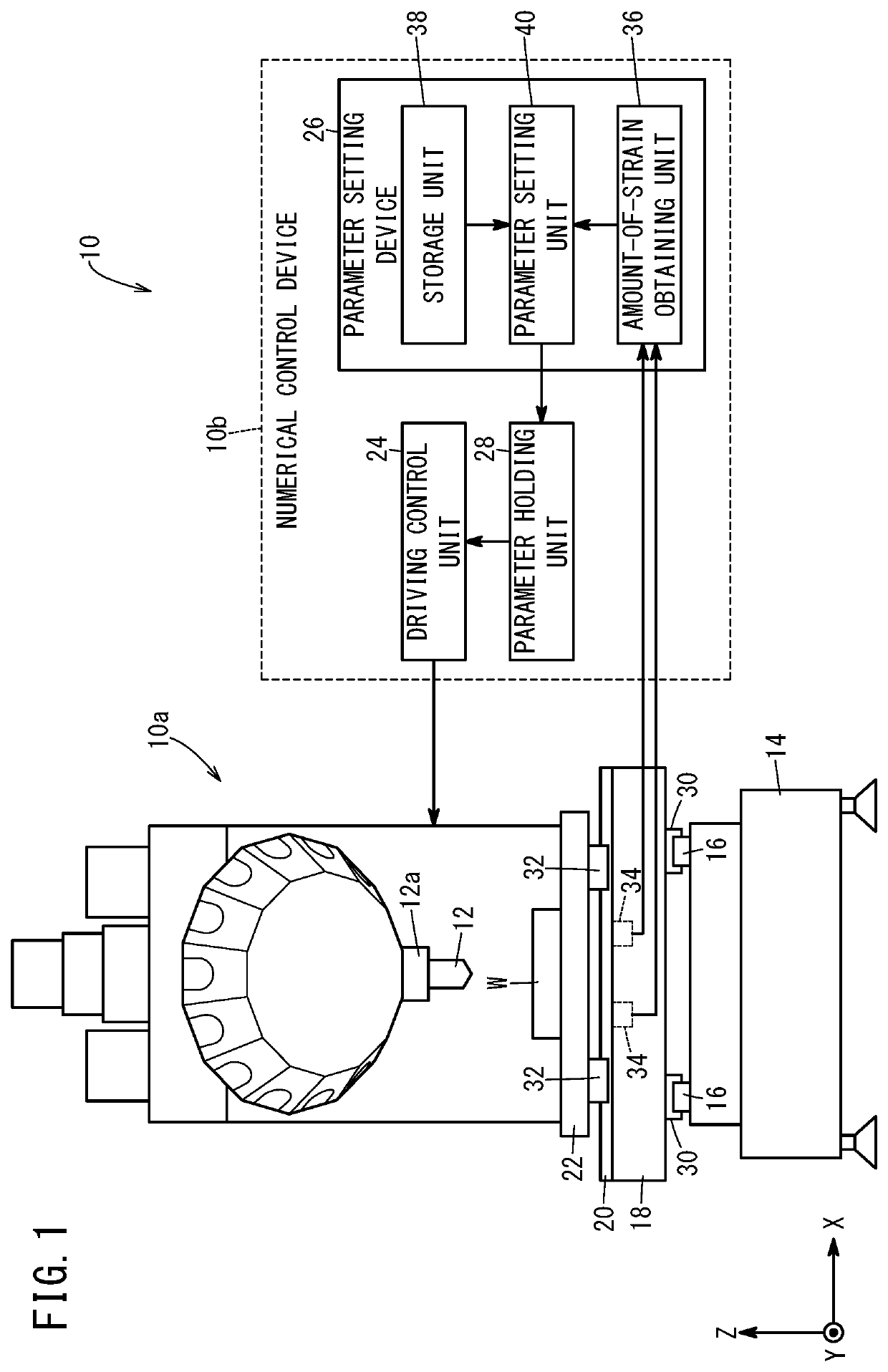
[0023]FIG. 1 is a diagram illustrating the configuration of a system 10 according to an embodiment. The system 10 is a machine tool that includes a machine tool body 10a and a numerical control device 10b. The system 10 may hereinafter be also referred to as a machine tool 10. The machine tool body 10a includes a tool 12, a spindle 12a, a bed 14, Y-axis rails 16, a saddle 18, X-axis rails 20, and a table 22. The numerical control device 10b controls the relative position between the tool 12 and the table 22 of the machine tool body 10a, whereby a workpiece W on the table 22 is machined. The numerical control device 10b includes a driving control unit 24, a parameter setting device 26, and a parameter holding unit 28.

[0024]The Y-axis rails 16 are disposed on the bed 14 so as to extend in the Y-axis direction. The saddle 18 has movement members 30 that are capable of linear movement on the Y-axis rails 16 in the Y-axis direction, and can thus move in the Y-axis direction on the Y-axis...

first modification

(First Modification)

[0040]FIG. 5 is a diagram illustrating the configuration of a system 42 according to a first modification. The system 42 is a machine tool and will hereinafter be referred to as a machine tool 42. The machine tool 42 is configured similarly to the machine tool 10 of FIG. 1. However, in the machine tool 42, a control device 46 that is different from the numerical control device 44 includes the parameter setting device 26. Providing the control device 46, such as a personal computer or microcomputer different from the numerical control device 44, with the function of the parameter setting device 26 makes it possible to improve the maintenance workability without considerably changing the configuration of the numerical control device 44. The numerical control device 44 here includes the driving control unit 24 and the parameter holding unit 28.

second modification

(Second Modification)

[0041]FIG. 6 is a diagram illustrating the configuration of a system 50 according to a second modification. The system 50 is a machine tool system that includes multiple machine tools 52 each including a numerical control device 56. In the second modification, the numerical control device 56 of one of the multiple machine tools 52 includes the parameter setting device 26. Here, each machine tool 52 includes the measurement units 34, and each numerical control device 56 includes the driving control unit 24 and the parameter holding unit 28.

[0042]In the second modification, the parameter setting device 26 sets parameters for each individual machine tool 52 on the basis of the amount of strain obtained from the measurement units 34 of each of the multiple machine tools 52. In this way, even when the system 50 includes an increased number of machine tools 52, the parameter setting device 26 provided in one numerical control device 56 can set parameters for each indi...


PUM


Abstract

A parameter setting device is configured to set a parameter relating to a speed of a table of a machine tool in accordance with the weight of an object placed on the table. The parameter setting device includes: an amount-of-strain obtaining unit configured to obtain the amount of strain of the table; a storage unit storing the parameter corresponding to the amount of strain; and a parameter setting unit configured to set, by using the storage unit, the parameter based on the amount of strain obtained by the amount-of-strain obtaining unit with the table standing still.

Description

CROSS-REFERENCE TO RELATED APPLICATION[0001]This application is based upon and claims the benefit of priority from Japanese Patent Application No. 2018-214658 filed on Nov. 15, 2018, the contents of which are incorporated herein by reference.BACKGROUND OF THE INVENTIONField of the Invention[0002]The present invention relates to a parameter setting device for setting a parameter relating to the speed of a table of a machine tool, a system having the parameter setting device, and a parameter setting method.Description of the Related Art[0003]In general, a machine tool performs machining operation with a machining jig, an additional axis table, etc. in addition to the workpiece being mounted on a table of the machine tool. It is therefore necessary to set parameters, such as a time constant relating to the speed of the table, in consideration of the weight of the objects mounted on the table. Conventionally, as described in Japanese Laid-Open Patent Publication No. 08-314531, in the ma...

Claims


Application Information

Patent Timeline
Patent Type & Authority Applications(United States)
IPC IPC(8): G05B19/409G05B19/408G05B19/401
CPCG05B19/409G05B2219/31294G05B19/4083G05B19/401G05B2219/37357G05B19/402G05B2219/37404G05B19/18
Inventor TAKEUCHI, NAOYAWATANABE, RIKIZOU
Owner FANUC LTD
Why Eureka
Try Eureka