
Touch sensor and electronic paper display panel

a technology of electronic paper and touch sensor, which is applied in the field of touch sensor and electronic paper display panel, can solve the problems of touch sensor being liable to not being able the touch sensor being unable to implement touch sensing operation, so as to achieve good sensing quality

Active Publication Date: 2020-05-07
E INK HLDG INC
View PDF0 Cites 0 Cited by
  • Summary
  • Abstract
  • Description
  • Claims
  • Application Information

AI Technical Summary

Benefits of technology

Enables reliable touch sensing functionality in electronic paper display panels by determining the relaxation frequency based on resistance and capacitance changes caused by touch objects, ensuring accurate touch position detection without interference from conductive layers.

Problems solved by technology

Generally, a touch sensor has to be exposed to air, and an internal layered structure thereof should not include, for example, an Indium Tin Oxide (ITO) conductive thin film or other similar conductive layer, so as to avoid covering other layered structures to cause a shielding effect and result in a fact that the touch sensor cannot implement a touch sensing operation.
When the touch sensor is integrated with the panel of the electronic paper display apparatus, the touch sensor is liable to unable to implement the touch sensing operation.

Method used


Image

  • Touch sensor and electronic paper display panel
  • Touch sensor and electronic paper display panel
  • Touch sensor and electronic paper display panel

Examples


Embodiment Construction

[0049]A plurality of embodiments is provided below to describe the invention, though the invention is not limited to the provided embodiments, and the provided embodiments may be suitably combined. A term “couple” used in the full text of the disclosure (including the claims) refers to any direct and indirect connections. For example, if a first device is described to be coupled to a second device, it is interpreted as that the first device is directly coupled to the second device, or the first device is indirectly coupled to the second device through other devices or connection means. Moreover, a term “signal” refers to at least a current, a voltage, a charge, a temperature, data, an electromagnetic wave or any other one or more signals.

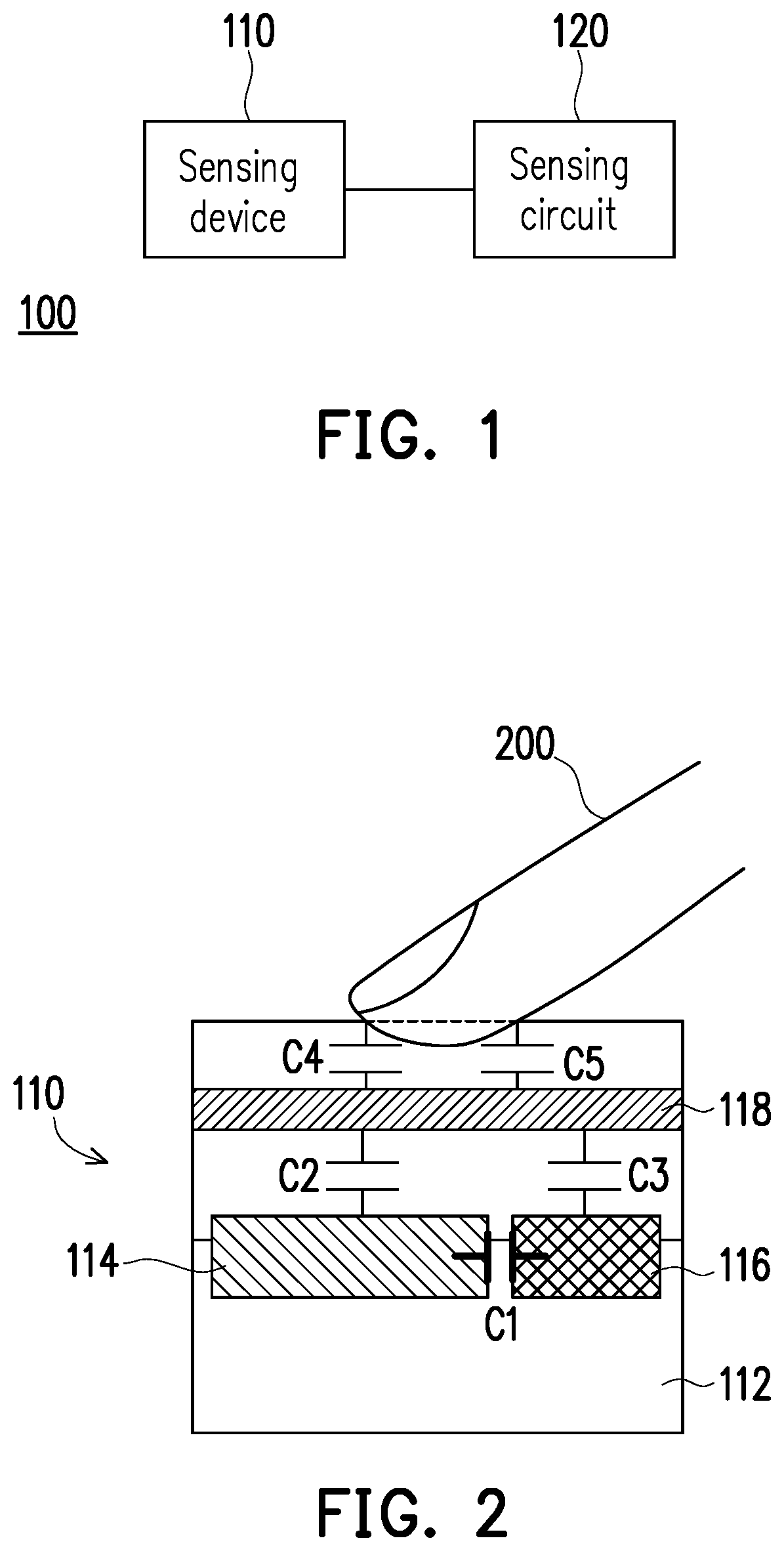
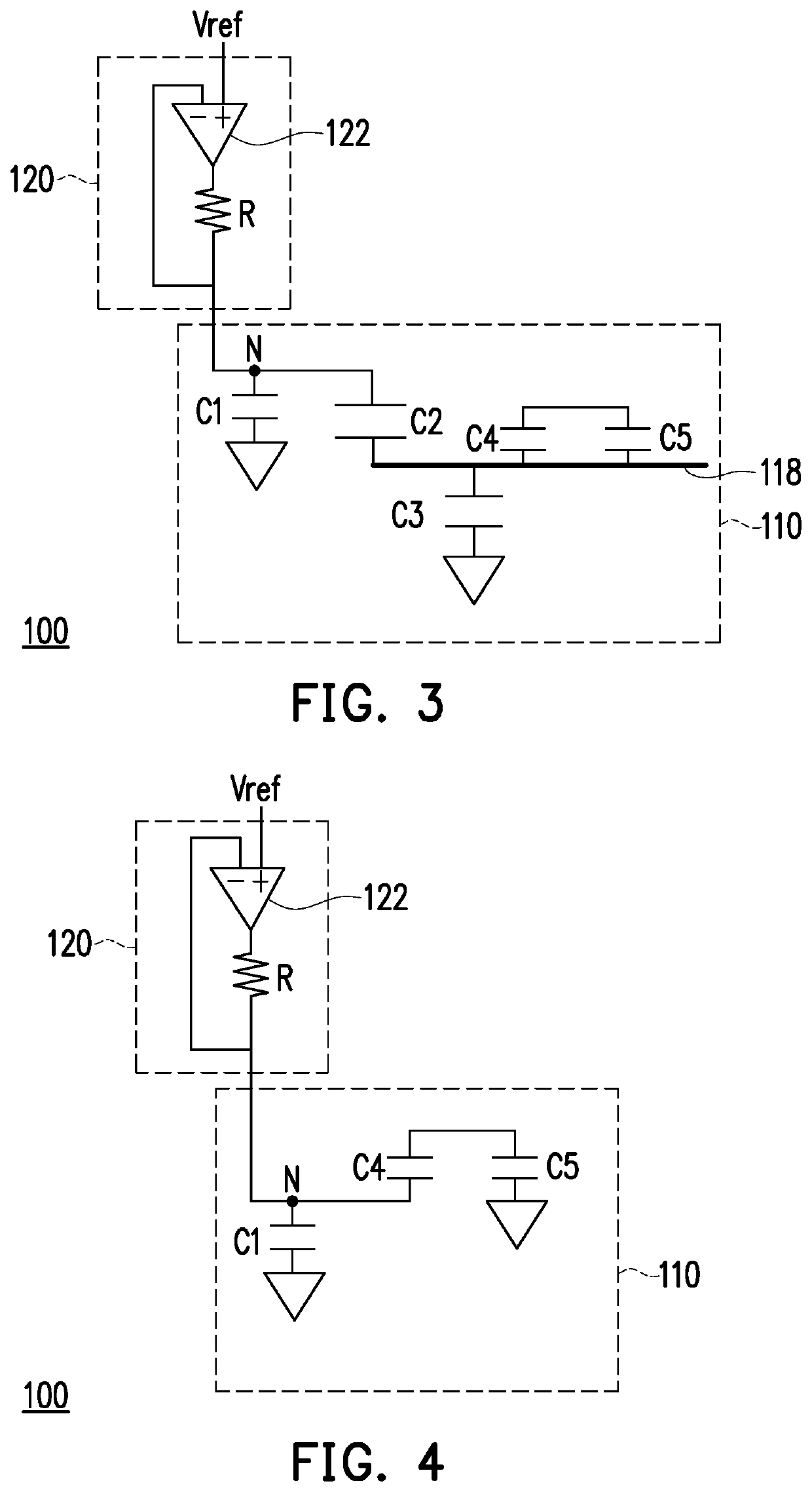
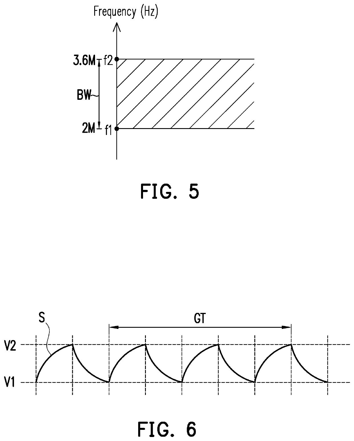
[0050]FIG. 1 is a schematic diagram of a touch sensor according to an embodiment of the invention. FIG. 2 is a structural schematic diagram of a sensing device of the embodiment of FIG. 1. FIG. 3 and FIG. 4 are respectively equivalent circuit schema...


PUM

PropertyMeasurementUnit
frequencyaaaaaaaaaa
frequencyaaaaaaaaaa
relaxation frequencyaaaaaaaaaa

Abstract

A touch sensor configured to sense a touch object is provided. The touch sensor includes a sensing device and a sensing circuit. The sensing device includes a substrate, a sensing electrode, a sensing common electrode and a shielding layer. The sensing electrode and the sensing common electrode are disposed on the substrate. The shielding layer is disposed on the sensing electrode and the sensing common electrode. The sensing circuit is electrically connected to the sensing device. The sensing circuit includes a resistor device. A relaxation frequency of a relaxation signal of the touch sensor is determined according to a resistance of the resistor device and / or a parasitic resistance of the sensing device. A pulse difference of the relaxation signal is changed by the touch object. The touch object is a conductor. An electronic paper display panel including the foregoing touch sensor is also provided.

Description

CROSS-REFERENCE TO RELATED APPLICATION[0001]This application is a continuation application of and claims the priority benefit of a prior application Ser. No. 16 / 368,887, filed on Mar. 29, 2019, now pending. The prior application Ser. No. 16 / 368,887 claims the priority benefit of Taiwan application serial no. 107116396, filed on May 15, 2018. The entirety of the above-mentioned patent application is hereby incorporated by reference herein and made a part of this specification.BACKGROUND OF THE INVENTIONField of the Invention[0002]The invention relates to a sensor and a display panel, and particularly relates to a touch sensor and an electronic paper display panel.Description of Related Art[0003]In recent years, since an electronic paper display apparatus has advantages of light and slim, durable, low power consumption that meets the requirement of energy saving and environmental protection, etc., it is widely applied to electronic readers (for example, electronic books, electronic ne...

Claims


Application Information

Patent Timeline
Patent Type & Authority Applications(United States)
IPC IPC(8): G06F3/044
CPCG06F3/044G06F2203/04107G06F3/0416G06F3/0446
Inventor CHENG, HSIAO-LUNGTSAI, SHU-FENHUNG, CHI-MAOLIANG, KUANG-HENG
Owner E INK HLDG INC
Learn More