Turbine rotor disk blade having a foot of curvilinear shape

a technology of rotor blades and blades, which is applied in the field of turbine rotor blades, can solve the problems of unsatisfactory overlap of rb>1/b>

Active Publication Date: 2020-05-07
SN DETUDE & DE CONSTR DE MOTEURS DAVIATION S N E C M A
View PDF0 Cites 0 Cited by
  • Summary
  • Abstract
  • Description
  • Claims
  • Application Information

AI Technical Summary

Benefits of technology

The invention can improve the distribution of stresses in the neck of a turbine rotor blade, which increases its lifespan. It can also improve the alignment of the blade's rotor vane, which helps maintain the orientation of grains in the vane and reduces the formation of harmful grains.

Problems solved by technology

It can be seen that overlap R1 is not satisfactory.

Method used


Image

  • Turbine rotor disk blade having a foot of curvilinear shape
  • Turbine rotor disk blade having a foot of curvilinear shape
  • Turbine rotor disk blade having a foot of curvilinear shape

Examples


Embodiment Construction

[0015]The aim of the invention is therefore to provide an at least partial solution to the requirements mentioned above, and to the disadvantages compared to the embodiments of the prior art.

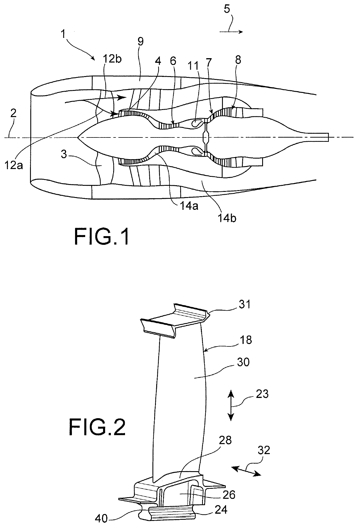
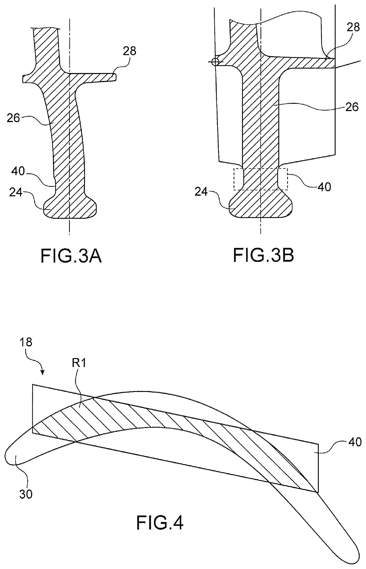
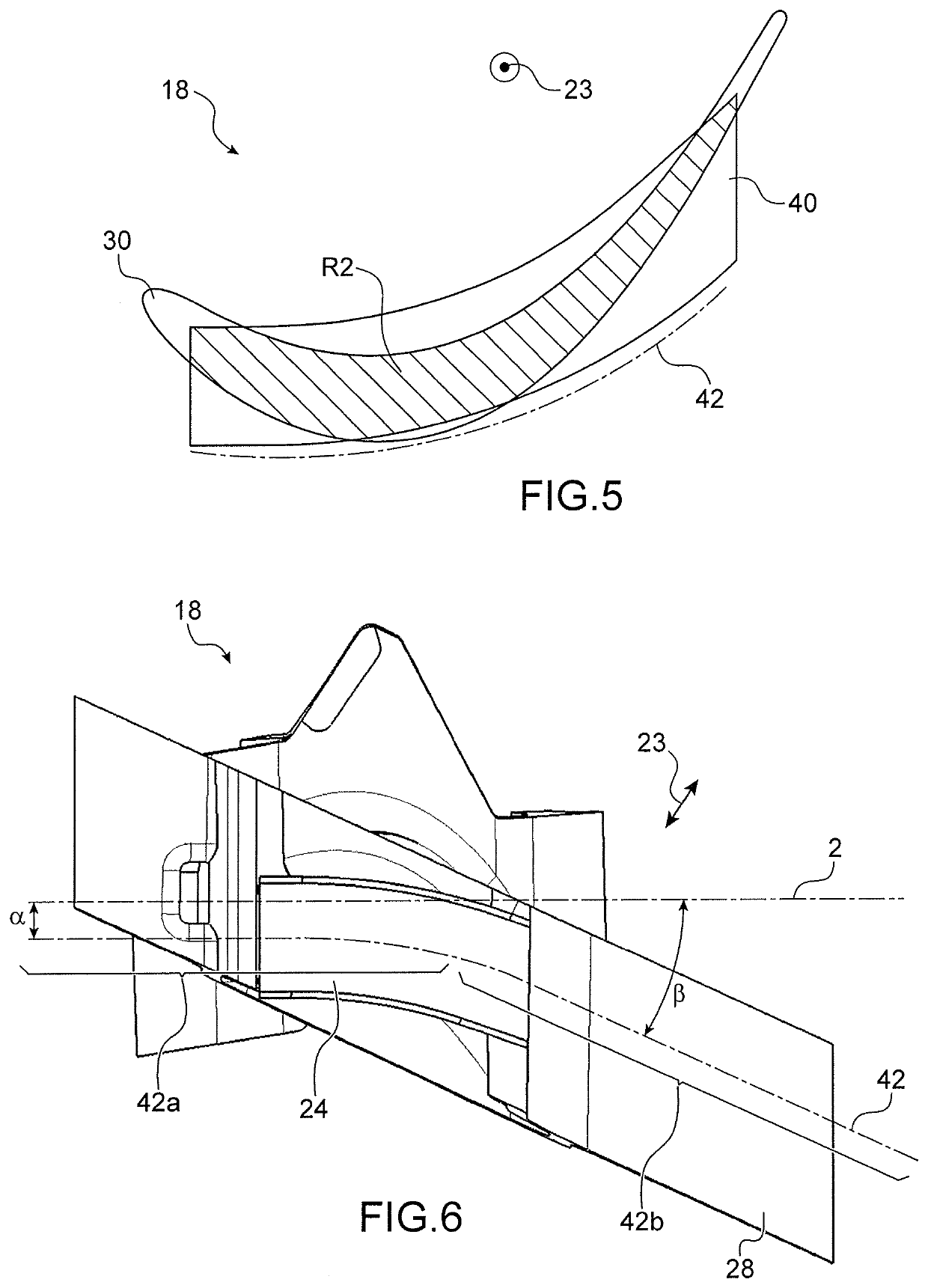
[0016]The object of the invention is therefore, according to one of its aspects, a rotor blade for a rotor disk of a turbine of an aeronautical turbomachine including, from the interior to the exterior, a blade foot root, a support, a platform and a rotor vane, where the root is connected to the support by a neck, characterised by the fact that the neck, and in particular the foot of the rotor blade including the root, the neck and the support, has a curvilinear profile defining, in a section in a plane perpendicular to the radial direction, a dished shape, extending in particular in a curvilinear axis, and by the fact that the said neck section thus overlaps at least 75%, and in particular at least 80%, of the section of the rotor vane, as a projection of the sections of the neck and of the rot...


PUM


Abstract

The main object of the invention is a rotor blade (18) for a rotor disk of a turbine of an aeronautical turbomachine including, in a radial direction (23) from inside to outside, a blade foot root, a support, a platform and a rotor vane (30), where the root is connected to the support by a neck (40), characterised by the fact that the neck (40) has a curvilinear profile defining, in a section in a plane perpendicular to the radial direction (23), a curved shape, and in that the said neck section (40) thus overlaps at least 75% of the section of the rotor vane (30), as a projection of the sections of the neck (40) and of the rotor vane (30) in a plane perpendicular to the radial direction (23), where the section of the rotor vane (30) joins with the platform.

Description

TECHNICAL FIELD[0001]The present invention relates to the general field of turbo machines, and more specifically to the field of turbine rotor blades for aeronautical turbo machines, and more specifically turbine rotor disks fitted with such blades, such as, for example, the disks described in patent application EP 1 264 964 A1.[0002]The invention applies to all types of land-based or aeronautical turbo machines, and in particular to aircraft turbo machines, such as turbojets and turboprop engines.STATE OF THE PRIOR ART[0003]FIG. 1 represents an aeronautical turbomachine 1, for example in this case a twin-body turbofan, which has a longitudinal central axis 2 around which its various components extend. It includes, from upstream to downstream in a main outflow direction 5 of the gases through this turbomachine, a fan 3, a low-pressure compressor 4, a high-pressure compressor 6, a combustion chamber 11, a high-pressure turbine 7 and a low-pressure turbine 8.[0004]Conventionally, afte...

Claims


Application Information

Patent Timeline
Patent Type & Authority Applications(United States)
IPC IPC(8): F01D5/12F01D5/30
CPCF01D5/12F01D5/30F05D2220/30F01D5/3007F05D2250/71F05D2300/606F05D2300/607
Inventor LOISEL, BRUNO MARC-ETIENNEPRAGASSAM, CARINE THUY-HUONGFLORENT, NICOLAS MARCCHAMBRE, MARION FRANCE
Owner SN DETUDE & DE CONSTR DE MOTEURS DAVIATION S N E C M A
Why Eureka
Try Eureka