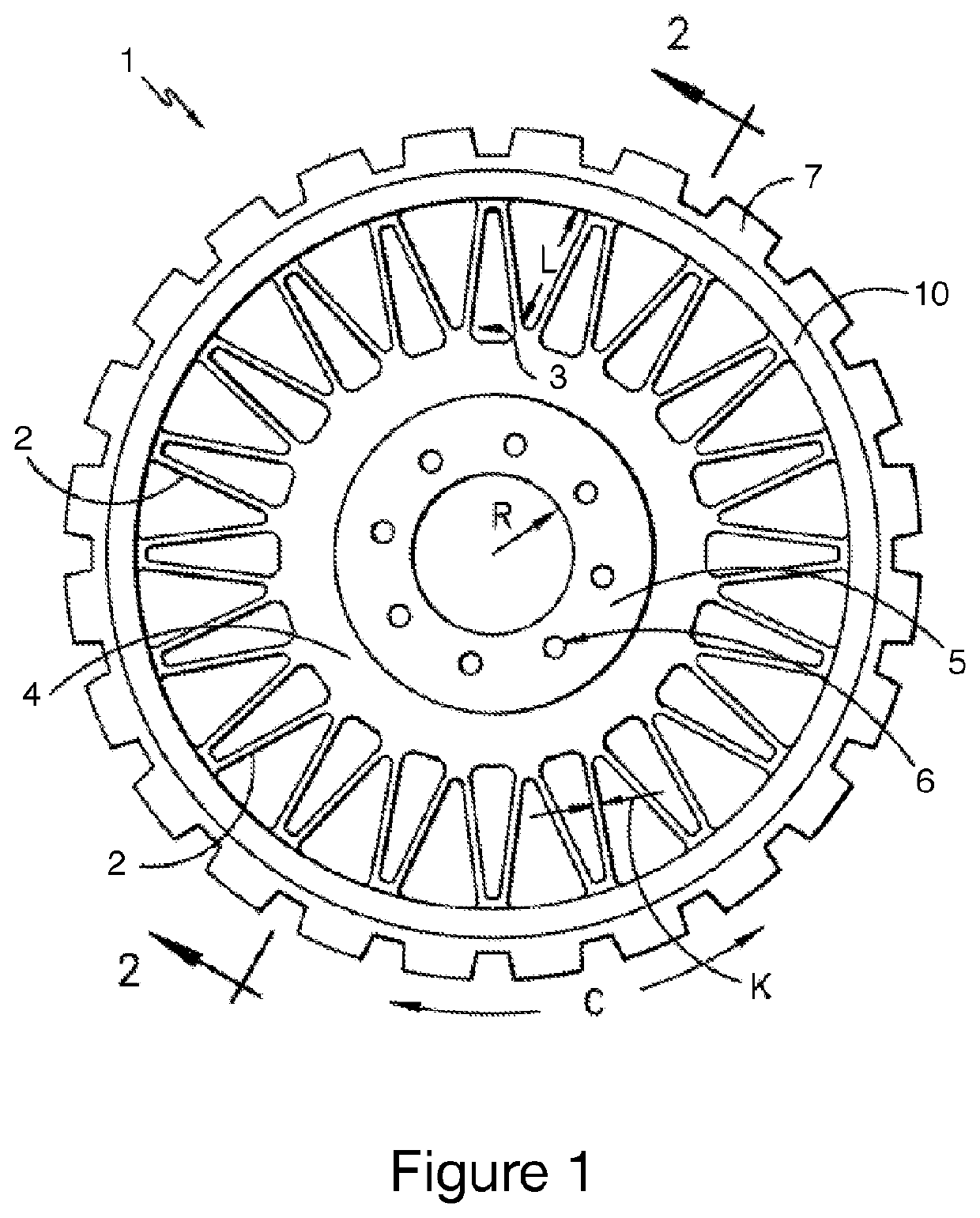
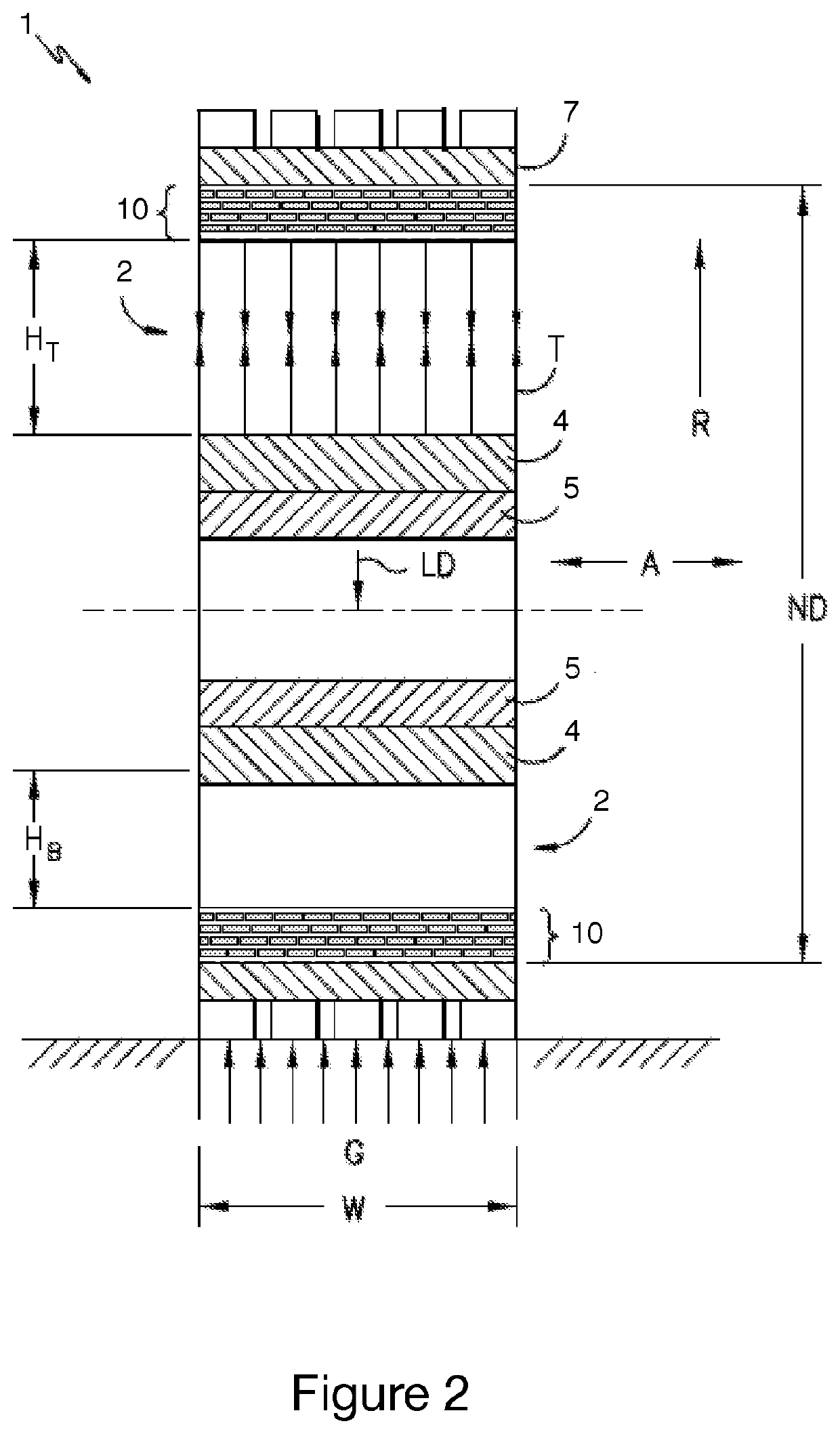
Non-pneumatic wheel comprising a circumferential reinforcement structure
- Summary
- Abstract
- Description
- Claims
- Application Information
AI Technical Summary
Benefits of technology
Problems solved by technology
Method used
Image
Examples
first embodiment
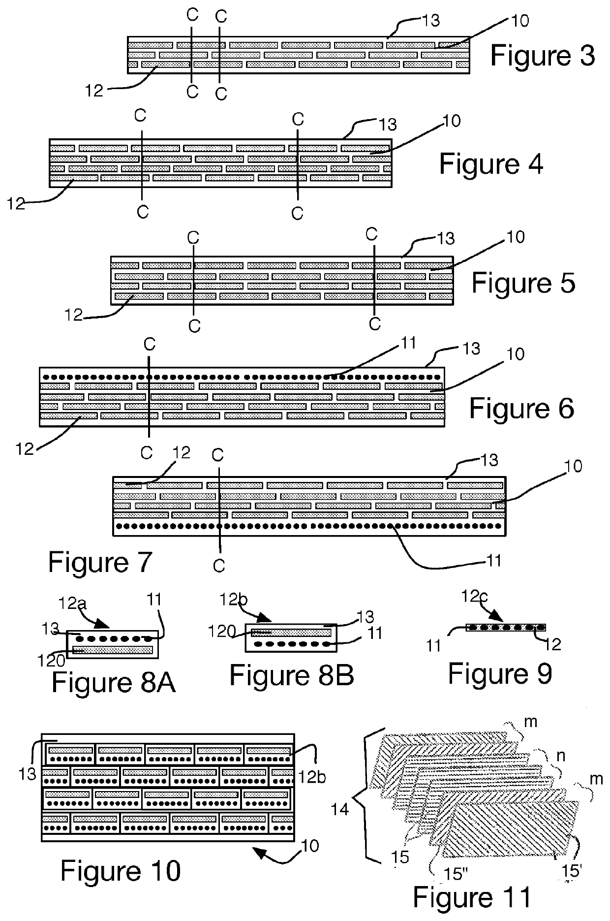
[0058]FIG. 3 illustrates an annular reinforcing structure 10 according to the invention. According to this embodiment, strips 12 made of a thermoplastic film are disposed side by side at an angle substantially in the region of 0 degrees, and more broadly at an angle less than substantially 12 degrees to the circumferential direction. The whole is embedded in a matrix 13 made up of an elastomeric compound, preferably a diene elastomeric compound. The staggered arrangement of the strips is realized for example by first winding-off starting at a given azimuth, and second winding-off starting at 180 degrees. As an alternative, the strips are positioned by first winding-off in one given axial direction, followed by second winding-off in the opposite axial direction.
[0059]The strips of a layer are separated by a region of rubber (or the elastomeric compound) referred to hereinafter as rubber bridge.
[0060]In the exemplary embodiment of FIG. 3, the crown 10 comprises three layers of strips ...
second embodiment
[0073]the strips is presented with reference to FIGS. 8A, 8B and 9. FIG. 8A illustrates an exemplary embodiment in which a thermoplastic film 120 as described hereinabove is surmounted by a layer 11 of reinforcing threads, preferably textile. The whole is embedded in a matrix 13 made up of an elastomeric compound, preferably a diene elastomeric compound, and forms a composite strip 12a. FIG. 8B presents an alternative form of composite strip 12b with a reverse geometry, the layer of threads 11 being arranged radially on the inside with respect to the thermoplastic film 120.
[0074]FIG. 9 illustrates a third example of composite strip 12c in which a layer of reinforcing threads 11 is integrated directly into a thermoplastic film 120. This alternative form has the additional advantages of greater lightness of weight and very high compactness.
[0075]FIG. 10 illustrates one example of a layout comprising four layers of strips, using strips such as those presented with reference to FIG. 8B;...
third embodiment
[0082]the strips 14 is described hereinbelow and illustrated in FIG. 11. The reinforcing strips 14 are made up of a laminate of at least 3 composite layers, each composite layer comprising mutually-parallel oriented high-modulus fibres (15, 15′, 15″) making an angle α with the circumferential direction (which is to say the longitudinal direction of the strip), coated in a polymer matrix. As a preference, the angle α formed by the fibres with the circumferential direction ranges from −90° to 90°.
[0083]Preferentially, the laminate comprises:[0084]n interior composite layers having fibres 15 of which the angle with the circumferential direction is 0°, n being a number greater than or equal to 1, preferably ranging from 1 to 20, more preferably ranging from 1 to 12, more preferably still from 1 to 6, these interior composite layers being juxtaposed with one another and flanked on each side respectively by m exterior composite layers,[0085]each exterior composite layer having fibres 15′,...
PUM
| Property | Measurement | Unit |
|---|---|---|
| Fraction | aaaaa | aaaaa |
| Fraction | aaaaa | aaaaa |
| Pressure | aaaaa | aaaaa |
Abstract
Description
Claims
Application Information
 - R&D
- Intellectual Property
- Life Sciences
- Materials
- Tech Scout
- Unparalleled Data Quality
- Higher Quality Content
- 60% Fewer Hallucinations
Browse by: Latest US Patents, China's latest patents, Technical Efficacy Thesaurus, Application Domain, Technology Topic, Popular Technical Reports.
© 2025 PatSnap. All rights reserved.Legal|Privacy policy|Modern Slavery Act Transparency Statement|Sitemap|About US| Contact US: help@patsnap.com


