Ceria supported palladium/calcium catalyst for hydrogenating co2 to dimethyl ether

a technology of palladium/calcium catalyst and dimethyl ether, which is applied in the direction of catalyst activation/preparation, metal/metal-oxide/metal-hydroxide catalyst, etc., can solve the problem of increasing the amount of cosub>2 /sub>emission, affecting the carbon efficiency of the process, and having a detrimental effect on the environment, so as to reduce the co2 conversion and improve the catalyst performance. , the selectivity of the catalys

Active Publication Date: 2020-04-30
KING ABDULAZIZ UNIV
View PDF2 Cites 4 Cited by
  • Summary
  • Abstract
  • Description
  • Claims
  • Application Information

AI Technical Summary

Benefits of technology

The present disclosure relates to a new catalyst for producing dimethyl ether from CO2 and H2. The catalyst is a CeO2 supported palladium catalyst containing a promoter and a catalytic material. The promoter includes Ca, and the catalytic material includes Pd and CeO2. The catalyst has a specific surface area of 50-100 m2 g. The atomic ratio of palladium to calcium ranges from 1:50 to 75:1. The atomic ratio of cerium to palladium ranges from 5:1 to 500:1. The method for preparing the catalyst involves heating a solution of Ce(III) salt and citric acid, mixing it with a solution of Pd(II) salt and an aqueous solution of Ca(II) salt, heating the mixture to form a gel, drying the gel, and calcining it in air to form a pre-catalyst. The catalyst is then contacted with CO2 and H2 in a reactor to produce dimethyl ether and byproducts. The conversion of CO2 and selectivity for dimethyl ether are maintained over a reaction period of 90 or more hours.

Problems solved by technology

To meet the energy demand, anthropogenic activity using fossil fuels has caused an increased amount of CO2 emission and has had a detrimental impact on the environmental system, i.e. global warming due to the greenhouse effect.
However, a major obstacle for the wide application of this technology is the generation of a significant amount of CO2. which substantially decreases the carbon efficiency of the process [Sun J, Yang G, Yoneyama Y, Tsubald N. Catalysis chemistry of dimethyl ether synthesis.

Method used


Image

  • Ceria supported palladium/calcium catalyst for hydrogenating co2 to dimethyl ether
  • Ceria supported palladium/calcium catalyst for hydrogenating co2 to dimethyl ether
  • Ceria supported palladium/calcium catalyst for hydrogenating co2 to dimethyl ether

Examples


example 1

Preparation of Pd / CeO2 Catalyst

[0089]The catalyst was synthesized via a sol-gel preparation method. In a typical preparation procedure for 2.0 g 5%Pd / CeO2 sample, 0.2165 g Pd salt (palladium nitrate) and 4.794 g of cerium salt (cerium nitrate) were dissolved into separate beakers filled with 30 cm3 deionized water The solutions were heated at 50° C. for 15 minutes applying continuous stirring. An aqueous solution containing citric acid (7.5522 g in 30 cm3 deionized water) present at 1:3 molar ratio of Pd and Ce metal ions to citric acid was also heated at 50° C. for 15 minutes. At first, the citric acid solution was added drop wise to the Ce salt solution, and the mixed suspension of Ce salt and citric acid was left to heat farther at the same temperature for 10 minutes. Then the Pd salt solution was added drop wise into the mixed suspension of Ce Salt and citric acid. The resulting mixture was heated at a temperature of 90° C. using an electrically driven heating plate with necessa...

example 2

Preparation of Ca-PcliCeO2 Catalyst

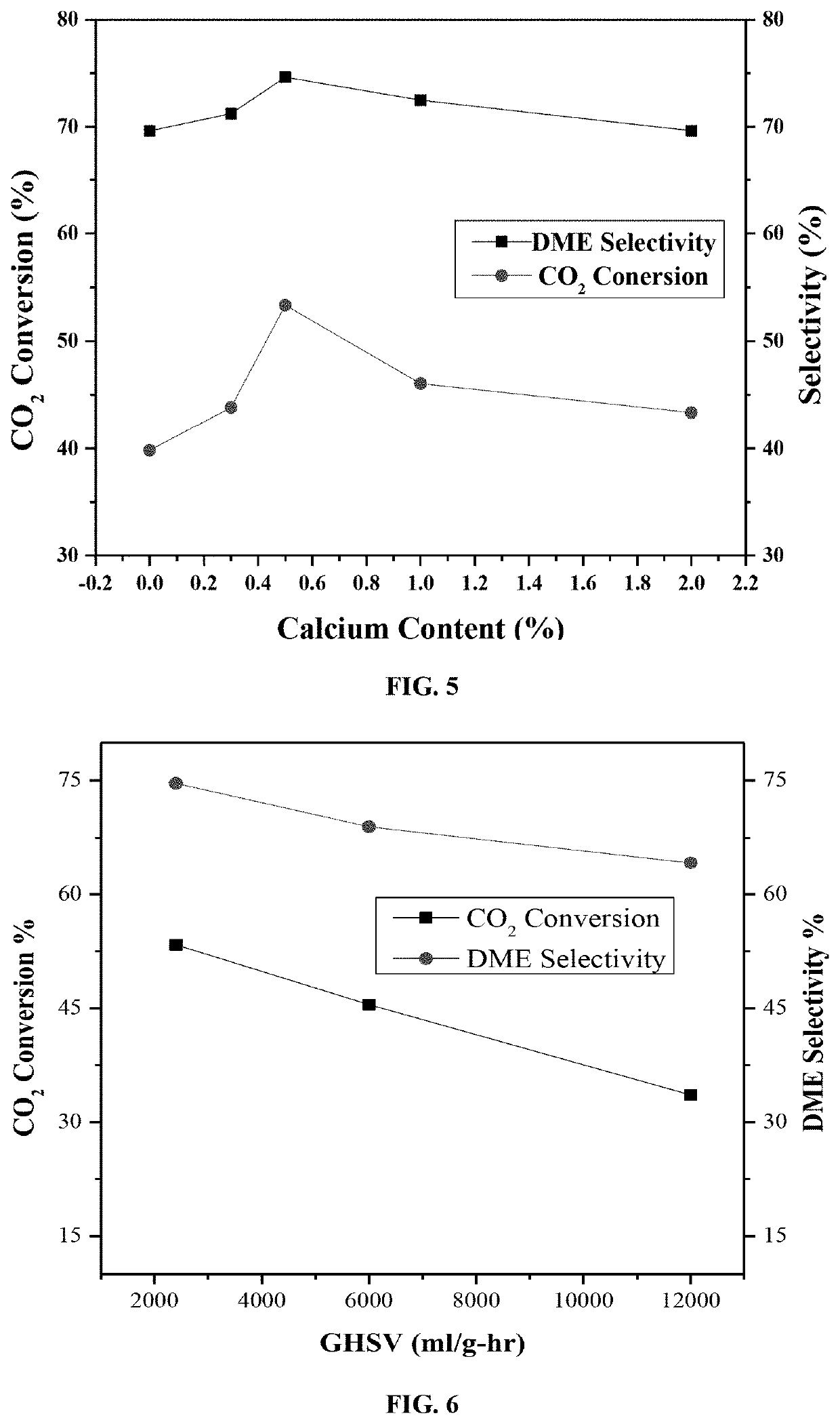
[0090]The catalyst was synthesized via a sol-gel preparation ethod. In a prototypical preparation procedure for 2.0 grains 0.5Ca5Pd / CeO2 sample, 0.2165 g of Pd, 0.2362 g Ca and 4.6925 g of Ce salts were each dissolved into separate beakers filled with 30 mL deionized water, and heated at 50° C. for 15 minutes with continuous stirring. An aqueous solution of citric acid (8.0356 g. 30 mL deionized water) with citric acid present at 1:3 molar ratio of Pd and Ce metal ions to citric acid was also heated at 50° C. for 15 minutes. At first, the citric acid solution was added drop wise to the Ce salt solution and the mixed suspension of Ce salt and citric acid was left to heat further at the same temperature for 10 minutes. Then Pd salt solution was added drop wise into the mixed suspension of Ce salt and citric acid, which was followed by the addition of the Ca salt solution. The resulting mixture was heated at a temperature of 90° C. using an electrical...

example 3

Catalytic Activity Testing of Ceria Supported Pd

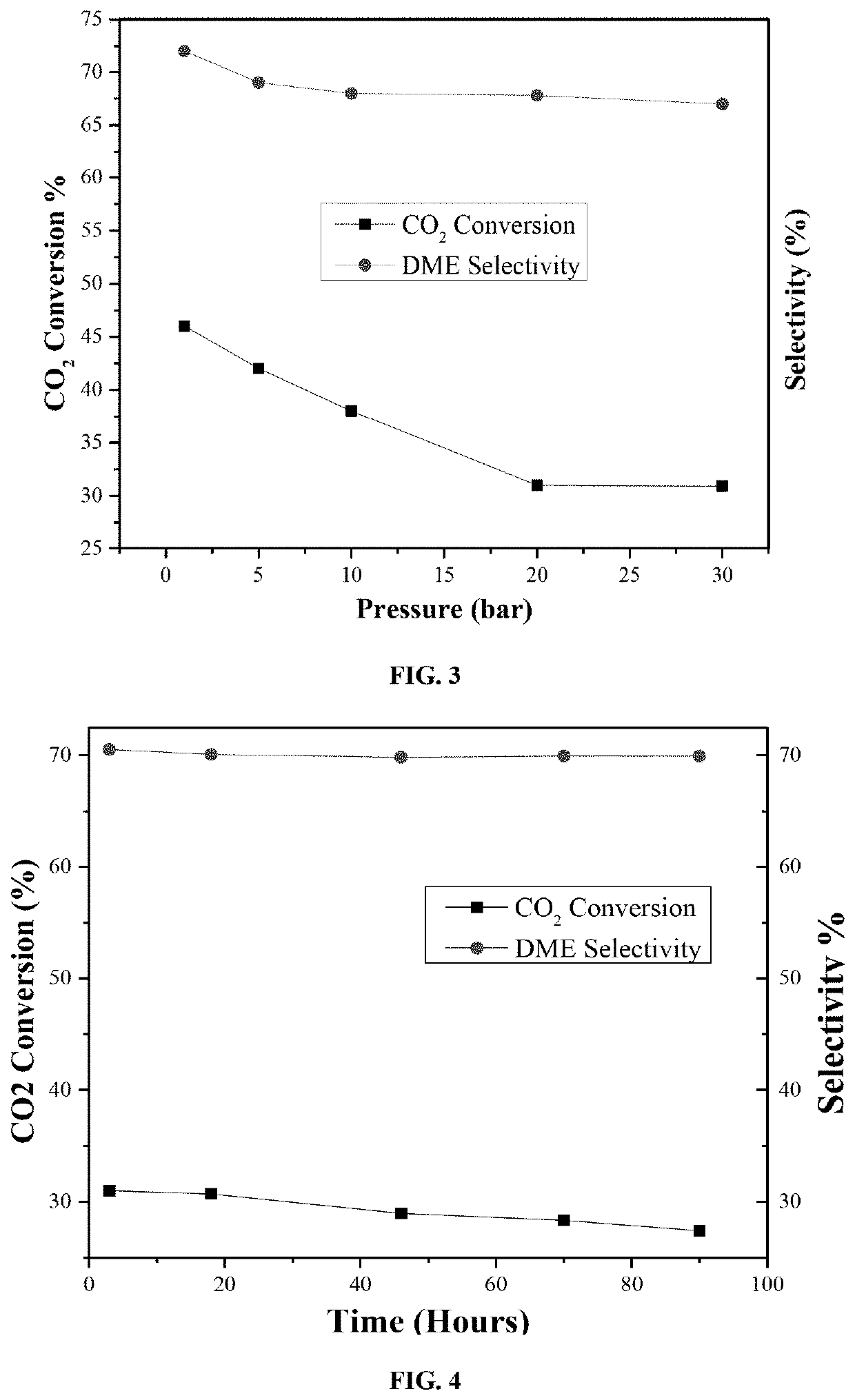
[0091]Catalytic activity tests of the disclosed catalyst samples were carried out in a MA-Effi reactor (PID Eng.& Tech., Spain) equipped with Bronkhorst mass flow and temperature controllers. The catalyst samples were tested at a temperature range of 270-350° C. employing a gas mixture with composition of CO2: H2=1:3 (Vol. ratio). Prior to each reaction, samples were reduced at 550° C. with 20 cm3 min−1 H2 flow (≥99.999%-Grade A) for one hour at atmospheric pressure.

[0092]In a general procedure, 0.5 grams of catalyst sample was placed into the stainless steel tubular reactor (i.d. 9.1 mm) and the temperature was raised in Ar flow of 15 cm3 min−1, (99.99%-Grade A) with a ramping rate of 5° C. / min. Once the reaction temperature was established, the H2 flow is turned on for 60 minutes. After reducing the catalyst sample, the temperature was brought back to reaction temperature under Ar flow.

[0093]The composition of product stream catalyze...


PUM

PropertyMeasurementUnit
temperatureaaaaaaaaaa
pressureaaaaaaaaaa
weightaaaaaaaaaa

Abstract

Catalysts for hydrogenation of CO2 to dimethyl ether. These catalysts comprise 0.1-10 wt % per total catalyst weight of a catalytic material containing Pd (e.g. metallic palladium), 0.05-5 wt % per total catalyst weight of a promoter containing Ca (e.g. metallic calcium), as well as 85-99 wt % of CeO2 as a catalyst support. Methods of preparing and characterizing the catalysts as well as processes for catalyzing the hydrogenation of CO2 to dimethyl ether and other byproducts such as methanol, carbon monoxide, and methane portrayed by reactant conversion., product selectivity, and catalyst stability are disclosed.

Description

TECHNICAL FIELD[0001]The present disclosure relates to a catalyst containing palladium and calcium promoter supported on cerium oxide, methods of preparation, and processes of utilizing the catalyst in dimethyl ether production via CO2 hydrogenation.DESCRIPTION OF THE RELATED ART[0002]The “background” description provided herein is for the purpose of generally presenting the context of the disclosure. Work of the presently named inventors, to the extent it is described in this background section, as well as aspects of the description which may not otherwise qualify as prior art at the time of filing, are neither expressly or impliedly admitted as prior art against the present invention.[0003]CO2 emissions are one of the major reasons for global warming and many technologies crucial to our society emit CO2. Ways to mitigate deleterious human impact on the environment include CO2 capture and development of non-CO2 emitting technologies for energy generation and chemical production.[00...

Claims


Application Information

Patent Timeline
Patent Type & Authority Applications(United States)
IPC IPC(8): B01J23/58B01J23/10B01J35/02B01J35/10B01J37/04B01J37/03B01J37/02B01J37/08B01J37/18C07C41/01
CPCB01J37/0236B01J37/18B01J35/026B01J35/1014B01J37/04B01J37/08B01J23/58B01J23/10C07C41/01B01J37/036B01J23/44B01J23/63B01J35/23B01J35/613C07C43/043B01J35/50
Inventor ZAMAN, SHARIF FAKHRUZMALIK, ALI SHANALZAHRANI, ABDULRAHIM AHMEDDAOUS, MUHAMMAD A.PETROV, LACHEZAR A.
Owner KING ABDULAZIZ UNIV
Why Eureka
Try Eureka