High density source spacing using continuous composite relatively adjusted pulse

Inactive Publication Date: 2020-04-23
CONOCOPHILLIPS CO
View PDF0 Cites 0 Cited by
  • Summary
  • Abstract
  • Description
  • Claims
  • Application Information

AI Technical Summary

Benefits of technology

The invention is a process for gathering seismic data to gather information about the structure of the earth. A plurality of seismic receivers are set up to receive the seismic energy, and a special type of seismic source delivers energy in the form of pulses. These pulses create a seismic energy wave in the earth, which is then recorded by the seismic receivers. By analyzing these recorded traces, the process identifies specific pulses and segments of data that overlap with the pulses, providing more data on the structure of the earth. The technical effect of this process is that it allows for more complete and accurate detection and analysis of geological structures.

Problems solved by technology

It is very expensive to acquire seismic data in marine environments.
Thus, once the survey is started, there is a lot of pressure to acquire data twenty-four hours a day, seven days a week.
A problem arises when another survey crew is collecting data in the same general area at the same time.
The two operations may contaminate one another and be forced to work out a time sharing arrangement where only one crew acquires data for a period of time and then waits while the other crew takes a turn.
A second concern in the collection of seismic data in marine environments is harm, injury or irritation of whales and other marine life due to the intensity of the energy coming off the seismic sources.
The power of these pulses in the water is presumed to be at least annoying to sea animals that use echo location like whales, dolphins and others.
Seismic surveying techniques may cause these animals to leave the area and some believe that it may be harmful to sea life.
This is particularly bad in a wide azimuth shooting where multiple vessels are towing guns and all guns are fired in a round-robin fashion.

Method used


Image

  • High density source spacing using continuous composite relatively adjusted pulse
  • High density source spacing using continuous composite relatively adjusted pulse
  • High density source spacing using continuous composite relatively adjusted pulse

Examples


Embodiment Construction

[0020]Turning now to the detailed description of the preferred arrangement or arrangements of the present invention, it should be understood that the inventive features and concepts may be manifested in other arrangements and that the scope of the invention is not limited to the embodiments described or illustrated. The scope of the invention is intended only to be limited by the scope of the claims that follow.

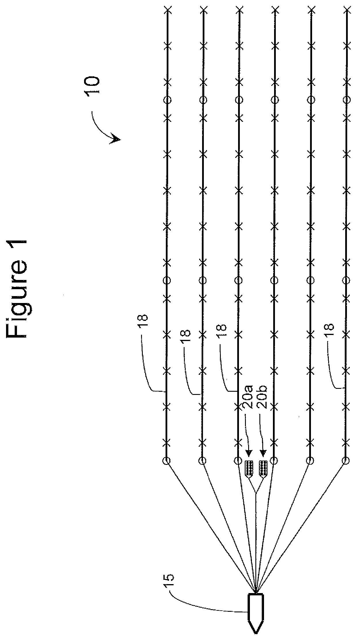
[0021]For the purpose of this discussion, an air gun seismic source will be used as an example of an impulsive seismic source. It should be understood that there are other impulsive sources that could be used with this invention, for example sparkers, plasma shots, steam injection sources or even explosive based sources. As shown in FIG. 1, a seismic acquisition system is generally indicated by the arrow 10. The system 10 includes a tow vessel 15 towing a number of streamers 18. Along each streamer 18 are a large number of seismic receivers, each indicated by the letter “x” a...


PUM


Abstract

The invention relates to continuously or near continuously acquiring seismic data where at least one pulse-type source is fired in a distinctive sequence to create a series of pulses and to create a continuous or near continuous rumble. In a preferred embodiment, a number of pulse-type seismic sources are arranged in an array and are fired in a distinctive loop of composite pulses where the returning wavefield is source separable based on the distinctive composite pulses. Firing the pulse-type sources creates an identifiable loop of identifiable composite pulses so that two or more marine seismic acquisition systems with pulse-type seismic sources can acquire seismic data concurrently, continuously or near continuously and the peak energy delivered into the water will be less, which will reduce the irritation of seismic data acquisition to marine life.

Description

CROSS-REFERENCE TO RELATED APPLICATIONS[0001]This application is a continuation application which claims benefit under 35 USC § 120 to U.S. application Ser. No. 13 / 185,169 filed Jul. 18, 2011, entitled “HIGH DENSITY SOURCE SPACING USING CONTINUOUS COMPOSITE RELATIVELY ADJUSTED PULSE,” which claims benefit under 35 USC § 119(e) to U.S. Provisional Application Ser. No. 61 / 365,631, filed Jul. 19, 2010 entitled “Unique Composite Relatively Adjusted Pulse” and U.S. Provisional Patent Application Ser. No. 61 / 365,663, filed Jul. 19, 2010 entitled “Continuous Composite Relatively Adjusted Pulse” and U.S. Provisional Patent Application Ser. No. 61 / 494,952, filed Jun. 9, 2011 entitled “High Density Source Spacing Using Continuous Composite Relatively Adjusted Pulse”, which are all incorporated herein in their entirety.STATEMENT REGARDING FEDERALLY SPONSORED RESEARCH OR DEVELOPMENT[0002]None.FIELD OF THE INVENTION[0003]This invention relates to emitting seismic energy into a marine environment...

Claims


Application Information

Patent Timeline
IPC IPC(8): G01V1/38G01V1/137
CPCG01V1/3861G01V1/137G01V1/375G01V1/3808G01V2210/127
Inventor EICK, PETER M.BREWER, JOEL D.JANISZEWSKI, FRANK D.
Owner CONOCOPHILLIPS CO
Why Eureka
Try Eureka