Lockout device for securing cable connector

Active Publication Date: 2018-10-25
3 CI PARTNERSHIP
View PDF0 Cites 2 Cited by
  • Summary
  • Abstract
  • Description
  • Claims
  • Application Information

AI Technical Summary

Benefits of technology

The patent describes a lockout device for securing a connector. The device includes two ring parts that are used to secure the device around the connector. The device also has an elongated protrusion that remains in the gap of the connector, preventing the connector from being slid out of the device. The lockout device covers the disconnection mechanism of the connector, making it difficult for the user to access it. The device can only be detached by using a secondary tool, which is inconvenient. The technical effect of the invention is to provide a secure and convenient way to lock the connector.

Problems solved by technology

Electrical connectors pose a safety hazard in environments having flammable gases or other ignitable substances suspended in the air.
An electrical connector with contacts that are energized may cause an arc to occur upon disconnection of the connector from a panel, and the arc may ignite flammable gases in the air and cause an explosion.
However, specialized electrical connectors often include other features in addition to the secondary tool unlock capabilities and are therefore generally more expensive than typical connectors that can be freely connected and disconnected without a secondary tool.
However, drilling a hole into a connector is both inconvenient and risky as modification may damage the structural or electrical integrity of the connector.
However, although achieving its intended goal of requiring a secondary tool for disconnection of a connector 104, the prior art connector lockout 100 of FIG. 1 is somewhat bulky and difficult to manufacture.

Method used


Image

  • Lockout device for securing cable connector
  • Lockout device for securing cable connector
  • Lockout device for securing cable connector

Examples


Embodiment Construction

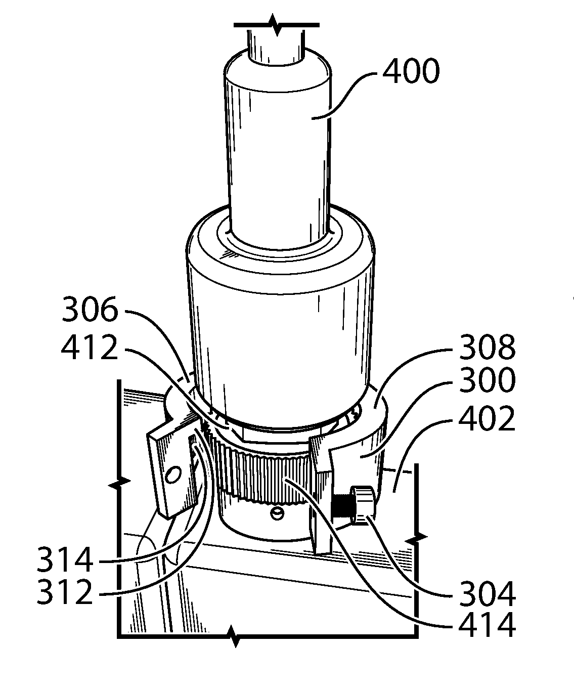
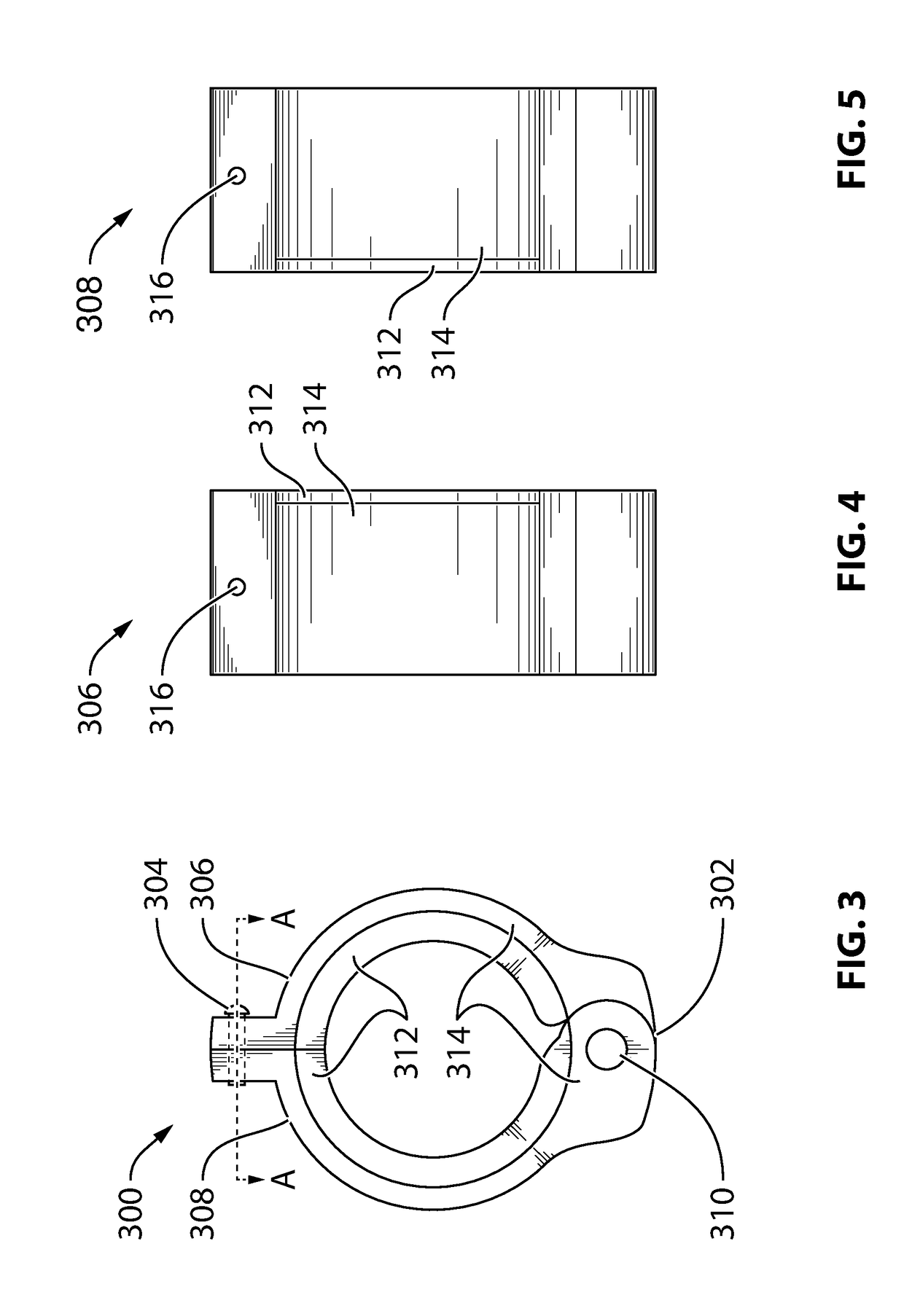
[0038]FIG. 3 illustrates a top view assembly diagram of a circular connector lockout device 300 with hinge assembly 302 and set screw 304 according to an exemplary embodiment of the present invention. The lockout device 300 includes a first ring portion 306 and a second ring portion 308 both generally formed by “C” shaped parts made of aluminum. The first ring portion 306 and the second ring portion 308 are secured to one another by the user of the hinge assembly 302 with integrated hinge pin 310 shown at the bottom area of FIG. 3 and the user adjustable set screw 304 shown at the top area of FIG. 3. Together, the first ring portion 306 and the second ring portion 308 form a tubular ring that can be utilized to surround the perimeter of a circular connector.

[0039]An inner facing protrusion is formed in this example by a circular ridge that acts as a locator ring 312 for holding the lockout device 300 captive on the connector while the first ring portion 306 is secured to the second ...


PUM


Abstract

A lockout device includes a first ring portion positioned around a first side of a connector. A second ring portion is positioned around a second side of the connector. A fastener allows a user to selectively secure the ring portions thereby forming a tubular ring surrounding the connector. An inner facing protrusion extends toward a center of the tubular ring and into a gap present on the connector. The inner facing protrusion remains in the gap of the connector regardless of movement of the lockout device about the connector while the first ring portion is secured to the second ring portion. The inner facing protrusion holds the lockout device captive around the connector and the tubular ring covers a disconnection mechanism of the connector. A secondary tool is required in order to detach the first ring portion from the second ring portion for accessing the disconnection mechanism of the connector.

Description

CROSS-REFERENCE TO RELATED APPLICATIONS[0001]This application claims the benefit of priority of Canadian Patent Application No. 2,965,010 filed Apr. 25, 2017, which is incorporated herein by reference.BACKGROUND OF THE INVENTION(1) Field of the Invention[0002]The invention pertains generally to cable connectors. More specifically, the invention relates to a lockout device requiring the use of a secondary tool in order to disconnect a cable connector.(2) Description of the Related Art[0003]Electrical connectors pose a safety hazard in environments having flammable gases or other ignitable substances suspended in the air. An electrical connector with contacts that are energized may cause an arc to occur upon disconnection of the connector from a panel, and the arc may ignite flammable gases in the air and cause an explosion.[0004]Country specific electrical safety codes have been developed to classify various types of explosive gas areas and to regulate safety requirements of electric...

Claims


Application Information

Patent Timeline
IPC IPC(8): H01R13/639
CPCH01R13/6397H01R13/623H01R13/639
Inventor CUNNINGHAM, STEVEN PAULCORASINITI, COLIN
Owner 3 CI PARTNERSHIP
Why Eureka
Try Eureka