
Flexible pipe connector suitable for effecting control and forced circulation of anticorrosive fluids through the annulus of the flexible pipe

a flexible pipe and connector technology, applied in the direction of hose connections, couplings, borehole/well accessories, etc., can solve the problems of corrosive effect of armour, failure mechanism, presence of water in the annulus, etc., and achieve the effect of reducing the corrosive

Active Publication Date: 2020-03-26
PETROLEO BRASILEIRO SA (PETROBRAS)
View PDF0 Cites 0 Cited by
  • Summary
  • Abstract
  • Description
  • Claims
  • Application Information

AI Technical Summary

Benefits of technology

The patent text describes a connector for flexible pipes that allows access and control of the pipe's annulus, which is the space between the inner and outer layers of the pipe. This connector is important because it allows for the forced circulation of corrosion-inhibiting fluids, like N2 or other non-corrosive fluids, through this annulus. This minimizes the corrosive effects caused by water and harmful gases, such as CO2 or H2S. In summary, the patent aims to provide a way to protect flexible pipes from corrosion and other damaging substances.

Problems solved by technology

The armouring is susceptible to corrosion by corrosive gases (CO2 and H2S) and water that permeates from inside the pipe, through the polymer of the barrier.
Any loss of hermeticity of the outer sheath also results in the presence of water in the annulus.
Corrosion may lead to failure mechanisms, such as stress corrosion—caused by CO2 or by H2S—and pitting corrosion.
However, this conventional technical solution is not sufficient to prevent corrosion due to condensation of water in the annulus or loss of integrity of the annulus through ingress of sea water.
In general, the annular space is very restricted, making circulation of the gases that have permeated and of other fluids difficult.
Consequently, removal or dilution to acceptable levels of corrosive fluids also becomes difficult, if forced circulation is not used or there is no change in the design features of the flexible pipe.
However, that document does not provide changes in the structure of the flexible pipe or connectors necessary to allow mitigation of the problems of corrosion in the armouring of the flexible pipe, such as SC—CO2 and pitting corrosion.

Method used


Image

  • Flexible pipe connector suitable for effecting control and forced circulation of anticorrosive fluids through the annulus of the flexible pipe
  • Flexible pipe connector suitable for effecting control and forced circulation of anticorrosive fluids through the annulus of the flexible pipe
  • Flexible pipe connector suitable for effecting control and forced circulation of anticorrosive fluids through the annulus of the flexible pipe

Examples


Embodiment Construction

[0073]First, it is emphasized that the following description is based on a preferred embodiment. However, as will be obvious to a person skilled in the art, the invention is not limited to this particular embodiment.

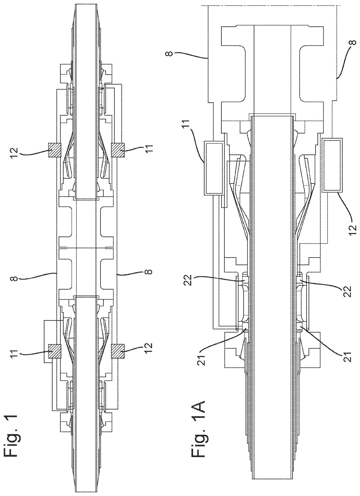
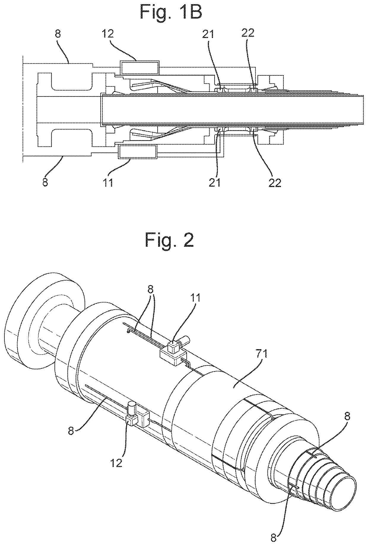
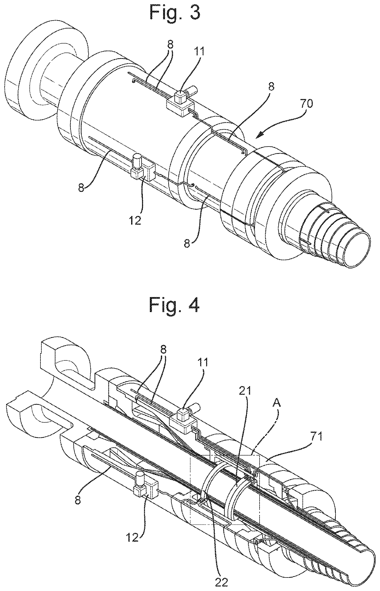
[0074]FIG. 1 shows two adjacent flexible pipe connectors suitable for effecting control and forced circulation of corrosion-inhibiting fluids through the annulus of the flexible pipe according to an optional configuration of the present disclosure. FIGS. 1A and 1B show schematically a first and a second flexible pipe connector as shown in FIG. 1.

[0075]The flexible pipe connector is suitable for effecting control and forced circulation of corrosion-inhibiting fluids through the annulus of the flexible pipe described, and comprises means for connecting to a flexible pipe.

[0076]Various connecting means between connectors and flexible pipes are known from the prior art, so a person skilled in the art will not have any difficulty in selecting the best means for this. Thus, th...


PUM

PropertyMeasurementUnit
flexibleaaaaaaaaaa
Flexibleaaaaaaaaaa
permeableaaaaaaaaaa

Abstract

A flexible pipe connector for effecting control and forced circulation of corrosion-inhibiting fluids through an annulus between inner and outer sheaths of a flexible pipe having multiple connected segments includes an attachment mechanism for connecting to an end of a segment of flexible pipe and at least two distributing rings for distributing corrosion-inhibiting fluid. The rings are configured to be positioned in the annulus of the flexible pipe, wherein at least one distributing ring has fluidic access to the annulus of the flexible pipe. This distributing ring is configured to be connected fluidically to at least one distributing ring, in an adjacent connector, that does not have fluidic access to the annulus, A distributing ring that does not have fluidic access to the annulus of the flexible pipe is configured to be connected fluidically to at least one distributing ring, in an adjacent connector, that comprises fluidic access to the annulus.

Description

CROSS-REFERENCE TO RELATED APPLICATION[0001]This application claims the benefit of priority to BR 10 2017 011388-4, filed 30 May 2017, which is incorporated herein by reference in its entirety.FIELD OF THE INVENTION[0002]The present invention relates to pipeline and riser technologies. More particularly, the present invention relates to connectors of pipelines with a system for control and forced circulation of fluids through the annulus of the pipeline.BACKGROUND OF THE INVENTION[0003]Petroleum production in the offshore environment makes wide use of ascending pipelines, known as risers. Such a pipeline, which may be flexible or rigid, collects the oil produced by the subsea well, and conveys it to a floating unit, and then to tankers or directly to onshore facilities.[0004]Flexible pipes of the “unbonded” type designed according to standards API Spec 17J and API RP 17B, the descriptions of which are incorporated herein by reference, possess armouring normally constructed of carbon...

Claims


Application Information

Patent Timeline
Patent Type & Authority Applications(United States)
IPC IPC(8): F16L58/18F16L11/08F16L11/22F16L33/01E21B17/08E21B41/02
CPCF16L11/22F16L11/081F16L58/18F16L33/01E21B41/02E21B17/085E21B17/02F16L37/08E21B17/01F16L58/00F16L11/12Y10T29/49826
Inventor CARPIGIANI DE ALMEIDA, MARCOSCARNEIRO CAMPELLO, GEORGERIBEIRO, JONATASMELLO SOBREIRA, RAFAEL GUIMARÃES DELOUREIRO JUNIOR, WALTER CARRARAPIZA PAES, MARCELO TORRES
Owner PETROLEO BRASILEIRO SA (PETROBRAS)
Learn More