Rail Systems for Fixing Fittings in a Cabin of a Vehicle

a technology for fixing fittings and rail systems, which is applied in the direction of aircraft accessories, seating arrangements, aircraft crew accommodation, etc., can solve the problems of additional expense and increased weigh

Active Publication Date: 2020-03-26
AIRBUS OPERATIONS GMBH
View PDF0 Cites 4 Cited by
  • Summary
  • Abstract
  • Description
  • Claims
  • Application Information

AI Technical Summary

Benefits of technology

[0004]Aspects of the invention may propose a particularly flexible solution for fixing fittings in a cabin of a vehicle, which is easily adapted to the fittings to be retained and causes no or only a slight additional weight.

Problems solved by technology

With this variant, some of the structural loads may indeed be transmitted to the floor rails, but both additional expense and higher weight are required.

Method used


Image

  • Rail Systems for Fixing Fittings in a Cabin of a Vehicle
  • Rail Systems for Fixing Fittings in a Cabin of a Vehicle
  • Rail Systems for Fixing Fittings in a Cabin of a Vehicle

Examples


Embodiment Construction

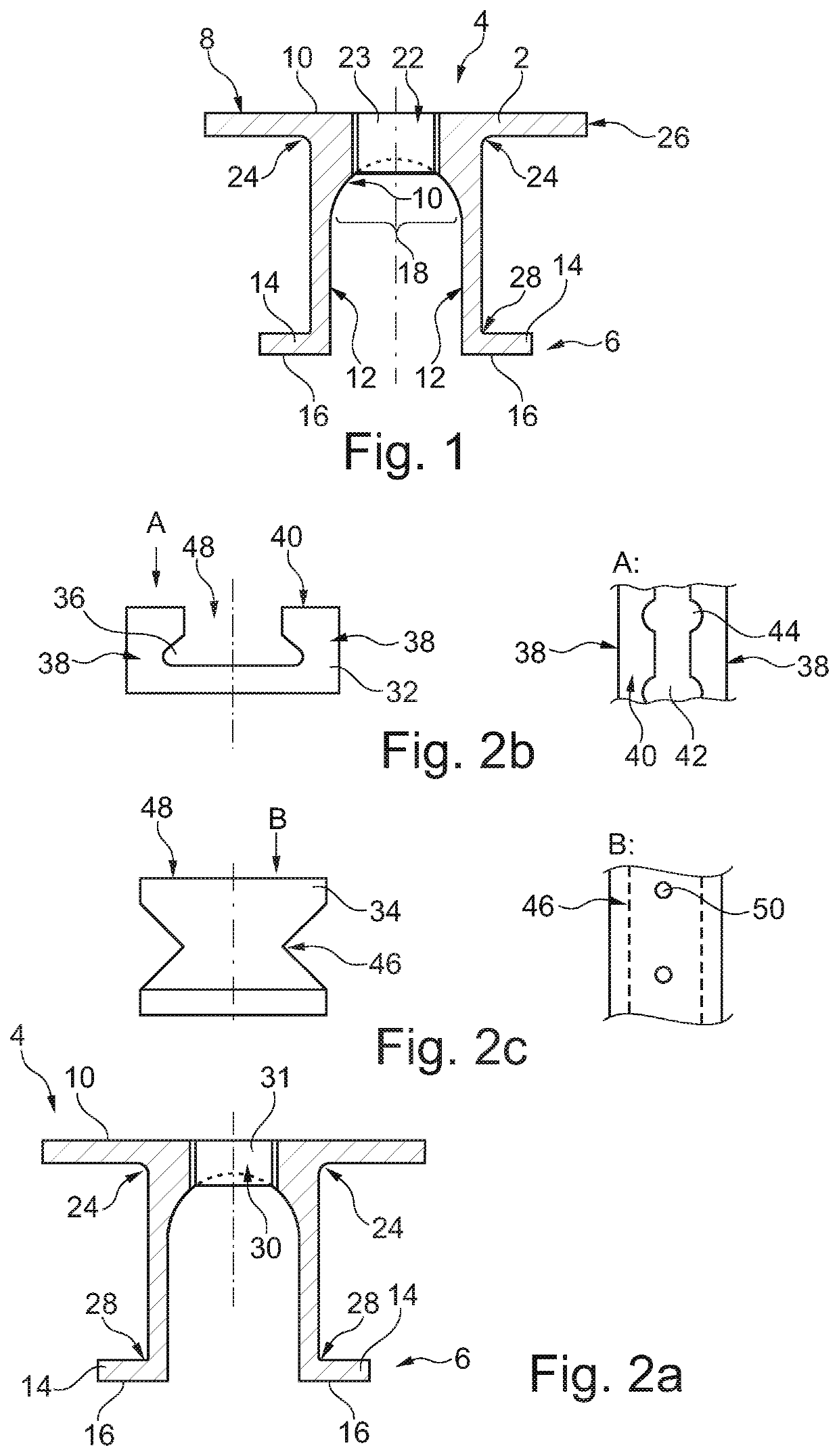
[0038]FIG. 1 shows a profile cross-section 2 of a first elongate rail body 4. A fixing side 6 is provided for fixing to a vehicle structure. Opposite this is a support side 8 having a support surface 10. Fittings to be installed may be placed thereon and attached.

[0039]The rail cross-section 2 has two legs 12 which lie opposite each other and are spaced apart from each other, and each run perpendicularly to the support surface 10. In the region of the fixing side, the legs 12 have outward flanges 14 which have a fixing surface 16 parallel to the support surface 10. The fixing surfaces may be laid against a primary structure of the vehicle in order then to fix the rail body to the structure via suitable fixing means.

[0040]In a region between the legs 12 and facing the support side 8, a transitional region 18 is arranged which for example is completely rounded. This means that the transitional portion 18 has a constantly shaped, trough-like curved surface 20. This is for example round...


PUM


Abstract

A rail system for fixing fittings in a cabin of a vehicle includes a first elongate rail body with a fixing side for fixing to a vehicle structure, an opposite support side with a support surface for receiving fittings, and a rail cross-section extending between the fixing side and the support side, and several fixing inserts which can be fixed along the support surface. The rail cross-section has two mutually opposing legs which are spaced apart from each other and run perpendicularly to the support surface, and the fixing inserts are configured so as not to protrude beyond the support surface.

Description

FIELD OF THE INVENTION[0001]The invention concerns a rail system for fixing fittings in a cabin of a vehicle, and a vehicle with a cabin and at least one such rail system installed therein.BACKGROUND OF THE INVENTION[0002]Rail systems for fixing fittings in a cabin of a vehicle are known. These are usually installed in a longitudinal extent of the cabin and, by means of a matrix-style top side, allow the arrangement and locking of fixing means which are connected to the fittings to be installed. In passenger aircraft, the seat or floor rails known as ATLAS rails are normally installed; these have a flat strip-like cavity on their top side which, via an elongate slot and openings through this, can receive locking bodies serving for fixing.[0003]For the installation of fittings which do not include seats or seat frames, other facilities may be required. Floor rails may be interrupted in this region, or the fittings may be coupled with conventional locking bodies so they can be attache...

Claims


Application Information

Patent Timeline
Patent Type & Authority Applications(United States)
IPC IPC(8): B64D11/06
CPCB64D11/0696B64C1/20
Inventor WERNER, SVENZYBALA, ANDREEILKEN, WOLFGANGTIRYAKI, MEMIS
Owner AIRBUS OPERATIONS GMBH
Why Eureka
Try Eureka