
Control device and control method

a control device and control method technology, applied in the direction of control devices, external condition input parameters, instruments, etc., can solve the problems of difficulty in identifying the color traffic signal misidentification, etc., to prevent control, and accurately estimate the traffic signal

Inactive Publication Date: 2020-03-05
HONDA MOTOR CO LTD
View PDF0 Cites 4 Cited by
  • Summary
  • Abstract
  • Description
  • Claims
  • Application Information

AI Technical Summary

Benefits of technology

The present invention is a control device for vehicles that uses external sensors to recognize traffic signals and participant movement. The device estimates the traffic signal based on the movement of the traffic participant and compares it to the recognized traffic signal. This prevents control based on mistaken identification of the traffic signal. The device can accurately identify the traffic signal and control the vehicle accordingly. The technical effects are improved safety and reliability of the vehicle control system.

Problems solved by technology

When capturing an image of a traffic signal device with a camera, if the image capturing environment is poor due to flashback, poor weather, or the like, it becomes difficult to identify the color compared to when the image capturing environment is good, and there is a concern that the traffic signal would be misidentified.
Furthermore, there are cases where misidentification of a traffic signal occurs due to a malfunction of the signal recognition function.

Method used


Image

  • Control device and control method
  • Control device and control method
  • Control device and control method

Examples


first embodiment

2. Process Performed by the Control Device 20

[0053][2.1. Main Process]

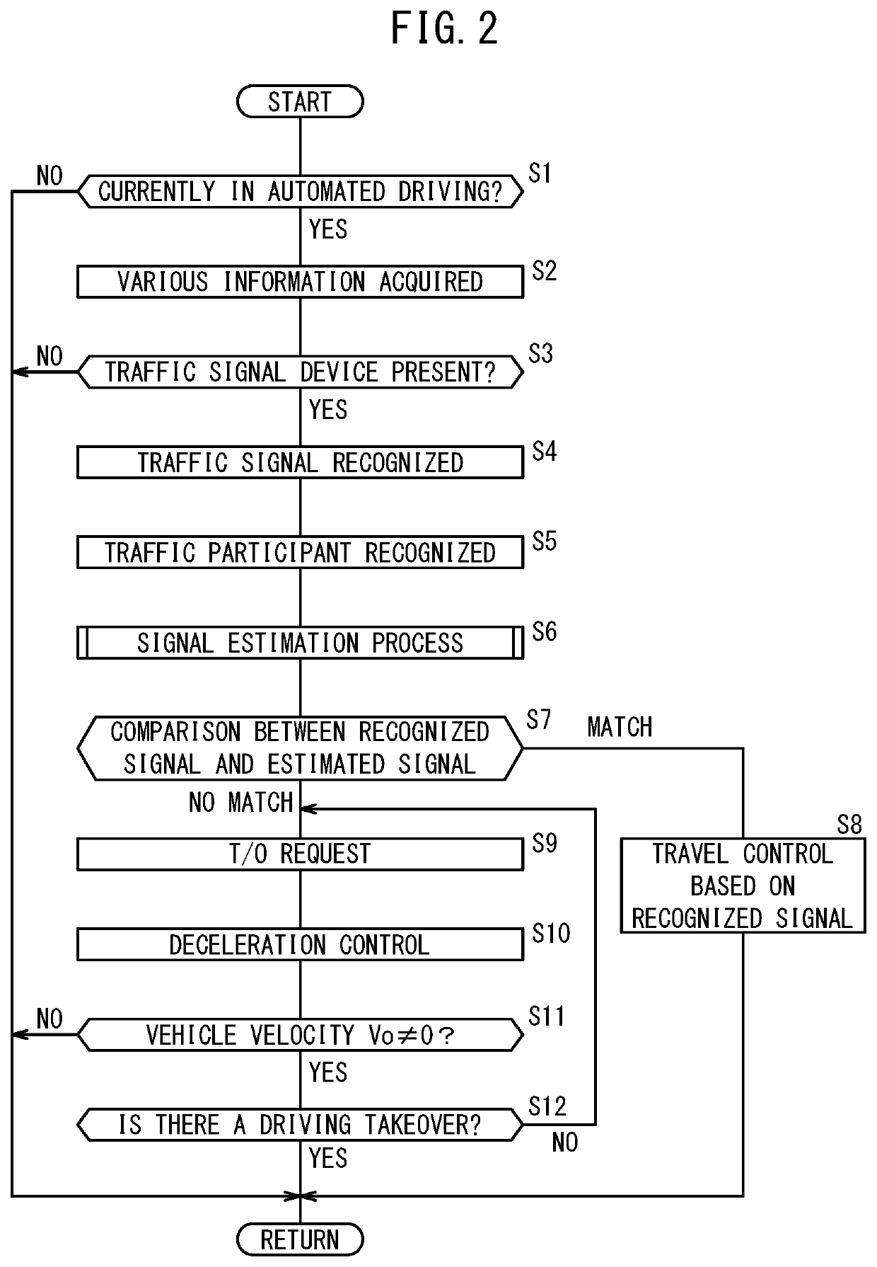
[0054]The following describes the main process performed by the control device 20, using FIG. 2. The process described below is performed periodically. At step S1, a determination is made concerning whether automated driving is currently being performed. If automated driving is currently being performed (step S1: YES), the process moves to step S2. On the other hand, if automated driving is not currently being performed (step S1: NO), the process ends for now. At step S2, various types of information are acquired. The control device 20 acquires the external environment information from the external environment sensor 12, and acquires the various signals from the vehicle sensor 14.

[0055]At step S3, the traffic signal recognition unit 60 determines whether a traffic signal device 110 is present. The traffic signal recognition unit 60 recognizes the presence of the traffic signal device 110 at a timing when the conto...

second embodiment

3. Process Performed by the Control Device 20

[0086][3.1. Main Process]

[0087]The following describes the main process performed by the control device 20, using FIG. 8. Among the processes described below, the processes of steps S31 to S38 are the same as the processes of step S1 to step S8 shown in FIG. 2, and therefore descriptions thereof are omitted.

[0088]If the process has moved from step S37 to step S39, the control unit 50 requests a warning. Specifically, the action plan unit 66 determines that the reliability of the signal recognition by the external environment recognition unit 46 is low. The notification control unit 72 receives this determination by the action plan unit 66, and outputs notification instructions for a warning to the notification device 28.

[0089]At step S40, the control unit 50 performs stopping control. Specifically, the action plan unit 66 creates an action plan for stopping. The trajectory generating unit 68 generates the scheduled travel trajectory in ac...


PUM


Abstract

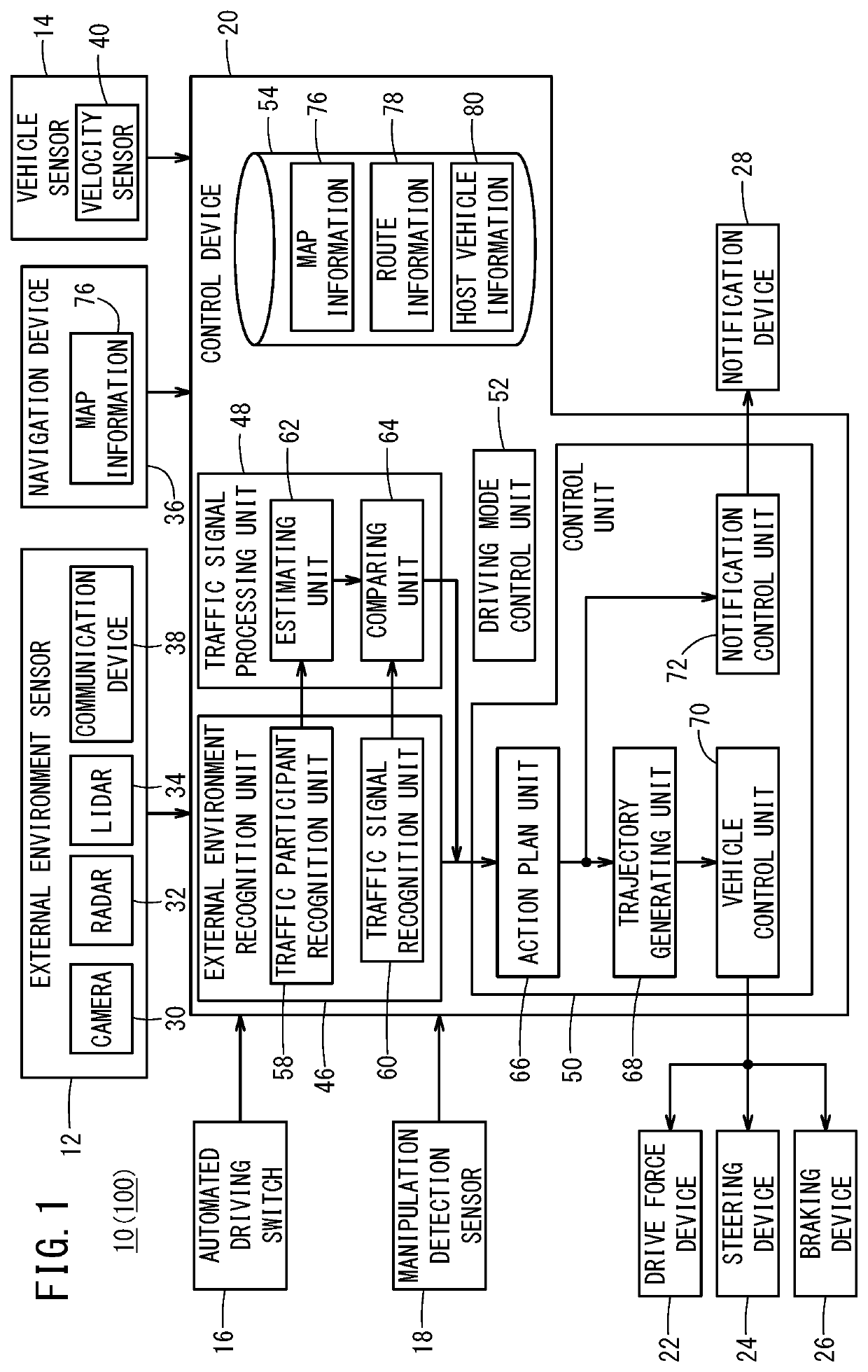
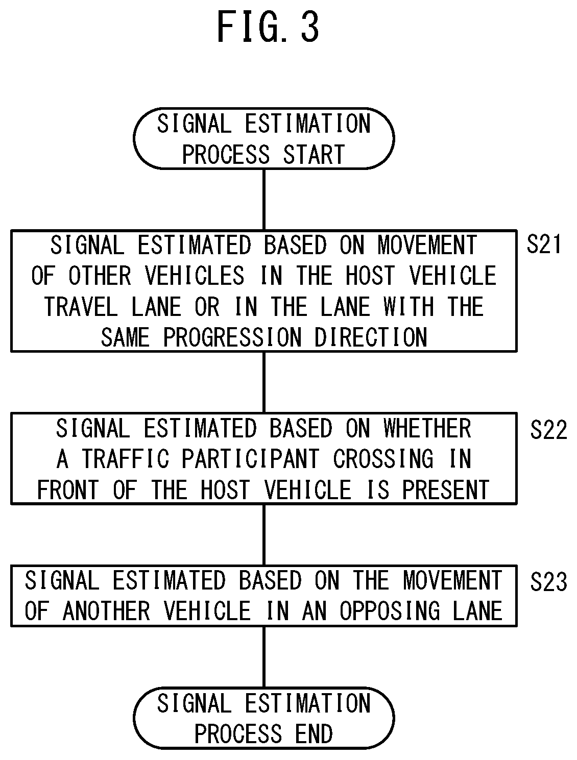
A traffic signal recognition unit recognizes a traffic signal of a traffic signal machine to be next followed on the basis of outside information. A traffic participant recognition unit recognizes the motion of a traffic participant on the basis of the outside information. A prediction unit predicts a traffic signal to be followed next on the basis of the motion of traffic participant recognized by the traffic participant recognition unit. A comparison unit compares the traffic signal recognized by the traffic signal recognition unit with the traffic signal predicted by the prediction unit. An action planning unit makes an action plan of a host vehicle on the basis of the comparison result of the comparison unit. A control unit carries out prescribed control on the basis of the action plan.

Description

TECHNICAL FIELD[0001]The present invention relates to a control device and a control method for performing prescribed control of a host vehicle using external environment information acquired by an external environment sensor.BACKGROUND ART[0002]Japanese Laid-Open Patent Publication No. 2009-015759 discloses a device for judging the color of a signal light based on an image of a traffic signal device captured by a camera. The light of a traffic signal device formed by an LED blinks when viewed microscopically. The objective of the device of Japanese Laid-Open Patent Publication No. 2009-015759 is to correctly recognize the color of the signal light, while assigning low reliability to images captured immediately after the LED lights up or immediately before the LED turns off. Specifically, this device selects signal light candidate information that includes the greatest brightness information among a plurality of pieces of signal light candidate information obtained in the recent pas...

Claims


Application Information

Patent Timeline
IPC IPC(8): G08G1/01B60W30/18B60W50/14
CPCB60W2555/60G08G1/0125B60W2050/143B60W50/14B60W2050/0072B60W30/18B60W2720/106B60W50/0205B60W2050/0215B60W50/0225B60W2554/4042B60W2554/4046B60W2554/805B60W2554/806G08G1/09623G08G1/0133B60W2420/403
Inventor MUKAI, TAKUYUKITANAKA, JUNHANAYAMA, KENIBUKA, JUNHORII, HIROAKIOCHIDA, JUN
Owner HONDA MOTOR CO LTD
Learn More