Power conversion device
a power conversion device and power technology, applied in the direction of open bus-bar installation, electrical apparatus construction details, support structure mounting, etc., can solve the problem that the space arranged for bending the external line cable becomes unnecessary, and achieve the effect of reducing or preventing an increase in the size, reducing or preventing the application of stress
- Summary
- Abstract
- Description
- Claims
- Application Information
AI Technical Summary
Benefits of technology
Problems solved by technology
Method used
Image
Examples
first embodiment
[0030]The overall configuration of a power conversion device 100 according to a first embodiment of the present invention is now described with reference to FIGS. 1 and 2. The power conversion device 100 is an uninterruptible power supply (UPS) or a power conditioning system (PCS) installed in a data center, for example.
[0031](Configuration of Power Conversion Device)
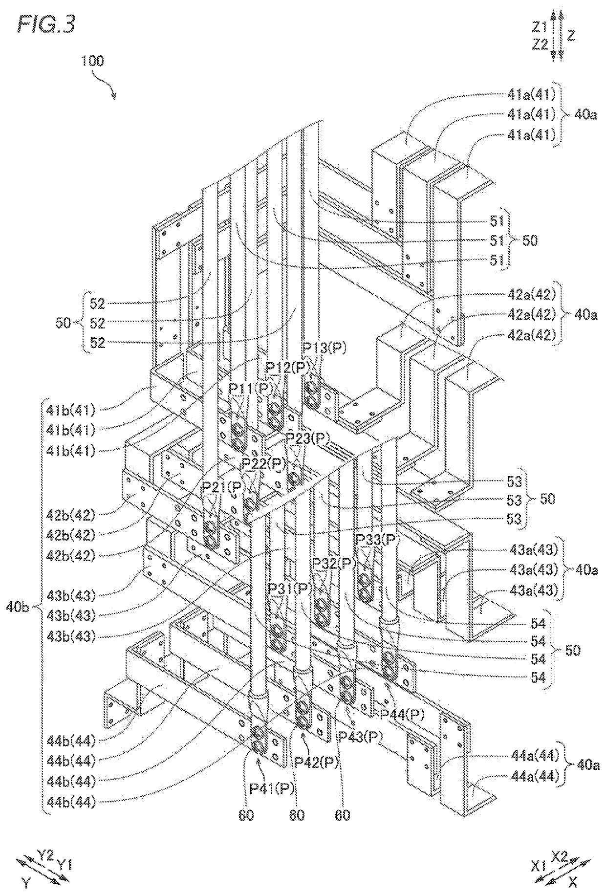
[0032]As shown in FIG. 1, in the power conversion device 100, a plurality of housings 10 is arranged adjacent to each other in a row. The plurality of housings 10 includes a plurality of housings 11 in which power conversion modules 20 (see FIG. 2) are housed and a housing 12 in which a control module 30 (see FIG. 2) is housed. In addition, the power conversion device 100 includes an external line connection cabinet 13 in which bus bars 40 that connect portions to each other inside the plurality of housings 10 and external line cables 50 pulled out of the power conversion device 100 are connected to each other. In the p...
second embodiment
[0059]A second embodiment of the present invention is now described with reference to FIG. 5. In this second embodiment, external line cables 250 are pulled downward, unlike the first embodiment in which the external line cables 50 are pulled upward. In the figure, the same structures as those of the first embodiment are denoted by the same reference numerals.
[0060]In a power conversion device 200 according to the second embodiment of the present invention, as shown in FIG. 5, bus bars 240 and the external line cables 250 pulled downward (in a Z2 direction) are connected to each other in an external line connection cabinet 13. The bus bars 240 include bus bars 241, 242, 243, and 244 corresponding to the bus bars 41, 42, 43, and 44 according to the first embodiment. In the second embodiment, the external line cables 250 are pulled out of the power conversion device 200 via an external line cable outlet 13a provided on the lower side (Z2 side) of the external line connection cabinet 1...
third embodiment
[0071]A third embodiment of the present invention is now described with reference to FIG. 6. In this third embodiment, external line cables 350 are pulled rearward, unlike the first embodiment in which the external line cables 50 are pulled upward and the second embodiment in which the external line cables 250 are pulled downward. In the figure, the same structures as those of the first embodiment are denoted by the same reference numerals.
[0072]In a power conversion device 300 according to the third embodiment of the present invention, as shown in FIG. 6, bus bars 340 and the external line cables 350 pulled rearward (in a Y2 direction) are connected to each other in an external line connection cabinet 13. The bus bars 340 include bus bars 341, 342, 343, and 344 corresponding to the bus bars 41, 42, 43, and 44 according to the first embodiment. In the third embodiment, the external line cables 350 are pulled out of the power conversion device 300 via an external line cable outlet 13...
PUM
 Abstract
Description
Claims
Application Information
 - R&D
- Intellectual Property
- Life Sciences
- Materials
- Tech Scout
- Unparalleled Data Quality
- Higher Quality Content
- 60% Fewer Hallucinations
Browse by: Latest US Patents, China's latest patents, Technical Efficacy Thesaurus, Application Domain, Technology Topic, Popular Technical Reports.
© 2025 PatSnap. All rights reserved.Legal|Privacy policy|Modern Slavery Act Transparency Statement|Sitemap|About US| Contact US: help@patsnap.com


