
Transport container

a technology for transporting containers and containers, applied in the field of transportation containers, can solve the problems of excessive relative motion of cargoes, prone to failure of cargo operation, and pronounced motion of the vessel, and achieve the effect of reducing corrosion and less resistance to high loads

Active Publication Date: 2020-02-20
REFLEX MARINE
View PDF0 Cites 3 Cited by
  • Summary
  • Abstract
  • Description
  • Claims
  • Application Information

AI Technical Summary

Benefits of technology

The present container has a rigid frame and energy absorbing elements to manage high side impact loads and protect the assets and surroundings in harsh sea operations. The container is designed for quick hooking and rapid operation and can be easily collapsed for easy handling. The combination of the rigid frame and energy absorbing elements provides better protection against unexpected impacts. The collapsible lifting point anchor can be collapsed manually and is positioned in a space similar to a previous container with conventional lifting eyes.

Problems solved by technology

Nevertheless, there are some critical scenarios where cargo operation is prone to failure posing some problems arisen.
Such weather can cause pronounced motions to the vessel in all degrees for freedom.
Lifting cargo from a deck of such a vessel, using a crane mounted on a separate structure, fixed or floating, means that the lifting operations are subjected to high relative motions, which can create dangerous conditions and excessive relative motions of the cargos when lifted.
In general, three key questions are taken into account when operating cargo in open water: the weight, safety and operating envelope:standard containers are heavy resulting in a low payload / net load ratio, also limiting the payload that can be transferred by cranes and vessels; moreover, mass in motion can be dangerous and cause several damage,heavy loads are difficult to control, and stiff aggressively shaped corners that can put crews at risk and cause severe damage to assets when working in restricted spaces, andfinally, delays can be caused due to restricted operating envelopes depending on the weather, limited load capacity of cranes, potential damage to assets and spillages or incidents hence impacting in overall performance.

Method used


Image

  • Transport container
  • Transport container
  • Transport container

Examples


Embodiment Construction

[0085]Container (1)

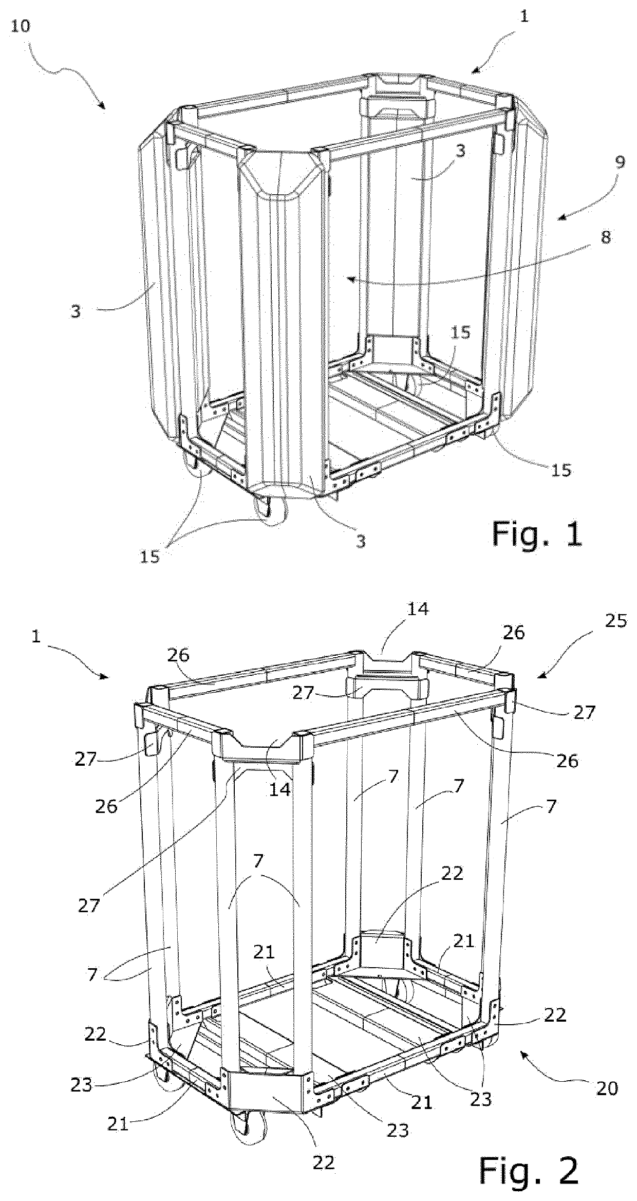
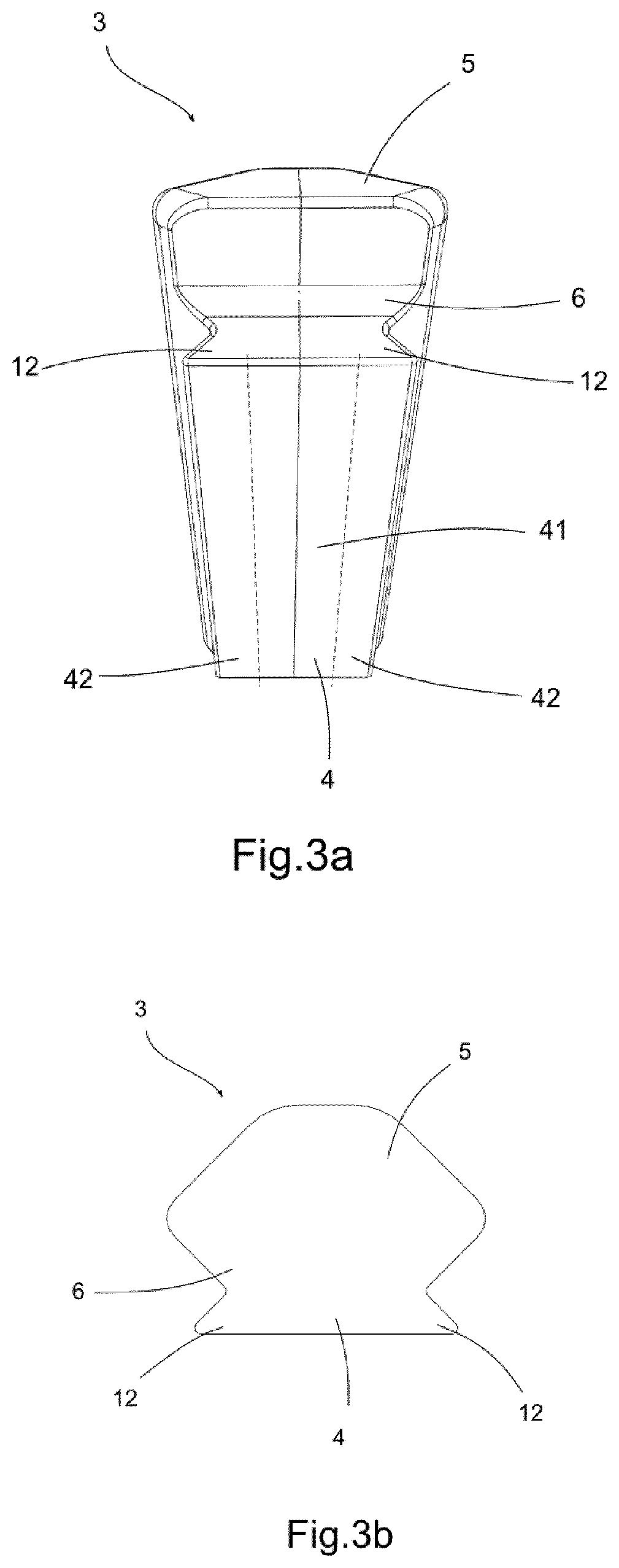
[0086]FIG. 1 shows a container (10) comprising:[0087]an internal surface (8) and an external surface (9),[0088]a rigid frame (1), which defines a plurality of container faces (11), wherein the confluence of two or more of said container faces (11) define edge portions (2), wherein one or more of the edge portions (2) are substantially chamfered, and[0089]one or more shock absorbing corner protectors (3) adapted for being mounted on the edge portions (2), wherein the corner protectors (3) comprise an inner face (4) and an outer face (5),

[0090]The edge portions (2) of the rigid frame (1) comprise one or more beams (7) arranged substantially in parallel to the direction of the confluence of two container faces (11).

[0091]By this configuration, there is a synergetic contrast between, a soft material able to absorb impacts, and a rigid material able to withstand loads and support the assets contained within the container (10).

[0092]In a particular example, the containe...


PUM


Abstract

Container adapted for cargo or personnel transport, the container being substantially prismatic, cylindrical or cubic in shape, wherein the container comprises: an internal surface and an external surface, a rigid frame, which defines a plurality of container faces, wherein the confluence of two or more of said container faces define edge portions being substantially chamfered, and one or more shock absorbing corner protectors adapted for being mounted on the edge portions, characterized in that the edge portions of the rigid frame comprise one or more beams arranged substantially in parallel to the direction of the confluence of two container faces, and the inner face of the corner protectors comprise at least a flange adapted for fitting in the one or more beams of the edge portions, such that the corner protectors substantially protrude from the external surface.

Description

TECHNICAL FIELD OF THE INVENTION[0001]The present invention belongs to the field of cargo or personnel containers and, more particularly, to the field of containers to be used in marine operations during harsh weather.[0002]In ordinary operation of cargo in marine conditions, for instance in a calm day, the hoisting and lifting up of cargo containers to be translated from vessels to working stations or vice versa, are performed safely for both surroundings and the integrity of the assets. Nevertheless, there are some critical scenarios where cargo operation is prone to failure posing some problems arisen.[0003]The more common critical scenario operating in marine conditions is harsh weather in particularly relating to the sea-state or wave conditions. Such weather can cause pronounced motions to the vessel in all degrees for freedom. Lifting cargo from a deck of such a vessel, using a crane mounted on a separate structure, fixed or floating, means that the lifting operations are sub...

Claims


Application Information

Patent Timeline
Patent Type & Authority Applications(United States)
IPC IPC(8): B65D90/02B62B3/00B62B5/00B63B27/30B65D90/00B65D90/18B63C9/06
CPCB65D90/02B63C9/06B65D90/0033B63B27/30B62B5/0006B65D90/18B62B3/002B63B27/16B65D90/00B62B3/00B65D90/0026B65D81/022B65D88/005B65D2590/0066B65D81/053
Inventor STRONG, PHILIP ANTON
Owner REFLEX MARINE
Learn More