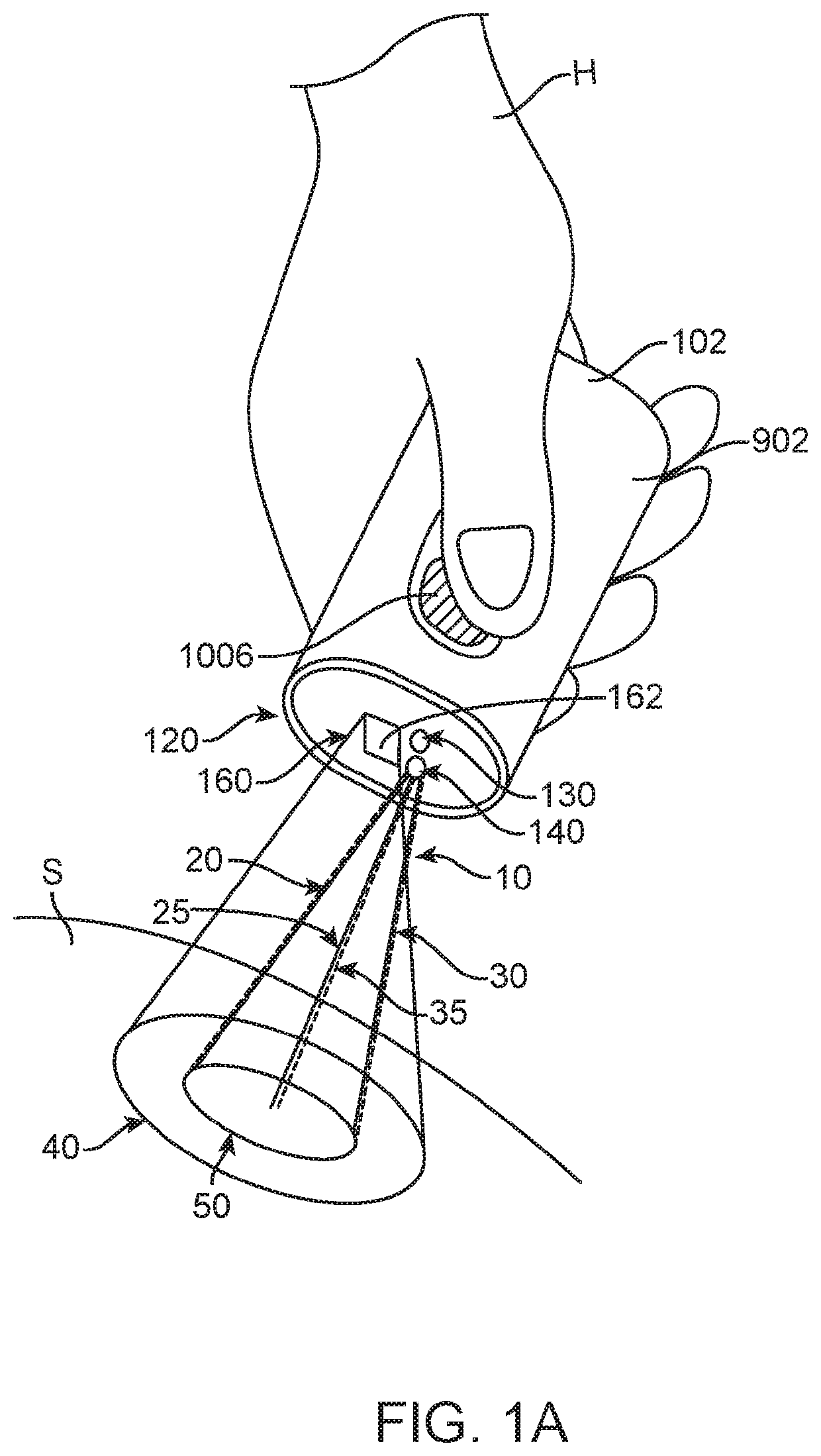
[0009]The present disclosure provides improved spectrometer methods and apparatus. A spectrometer may be used to determine one or more spectra of an object, and the one or more spectra may be associated with one or more attributes of the object that are relevant to the user. While the spectrometer can take many forms, in many instances the spectrometer comprises a hand held spectrometer with wavelength multiplexing in which a plurality of wavelengths are used to illuminate the object and measure the one or more spectra. The handheld spectrometer can be configured with a visible aiming beam to allow the user to determine the measured region of the object. The visible aiming beam may comprise the spectrometer measurement beam, or a separate beam. When the visible aiming beam comprises the spectrometer measurement beam, the spectrometer measurement beam comprises sufficient energy for the user to see the measurement beam illuminating the object. When the visible aiming beam comprises a separate beam, the visible aiming beam comprises sufficient energy for the user to see a portion of the aiming beam reflected from the object. The visible aiming beam and measurement beam can be arranged to at least partially overlap on the sample, such that the user has an indication of the area of the sample being measured. The spectrometer may comprise a field of view, and the measurement beam illuminating the sample may occupy only a portion of the field of view of the spectrometer, such that the region of the sample measured is defined with the measurement beam. The measurement beam may overlap with the visible aiming beam such that the visible aiming beam identifies the measurement area of the sample for the user. This identification of the area of the sample to be measured can help the user aim the hand held spectrometer and provide improved measurement accuracy with decreased artifacts. The measurement beam can be coupled to the aiming beam in one or more of many ways with one or more of many configurations, such as a coaxial configuration in which the measurement bean and aiming beam extend coaxially together along a shared optical axis.
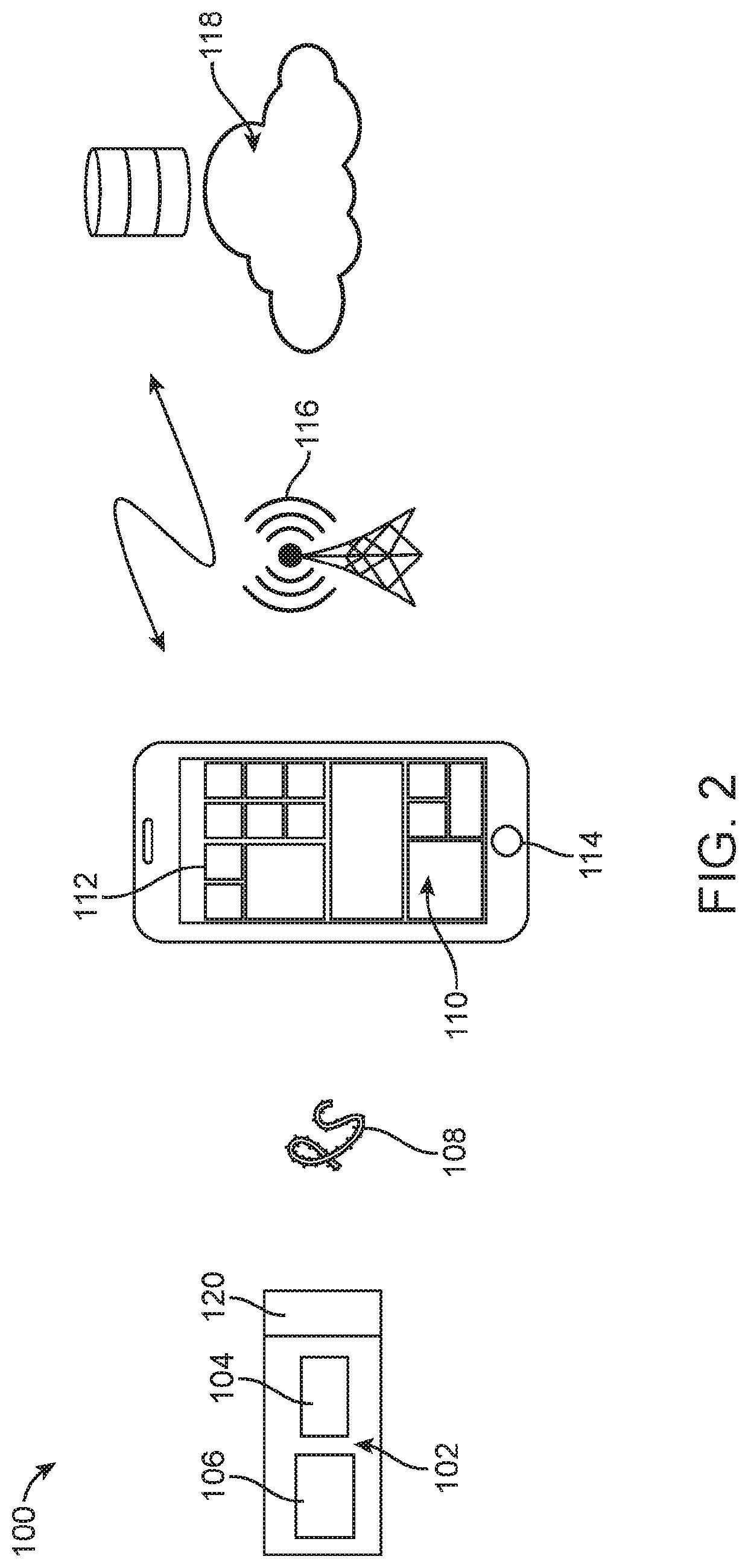
[0010]The spectral data of the object can be used to determine one or more attributes of the object. In many instances, the spectrometer is coupled to a database of spectral information that can be used to determine the attributes of the object. The spectrometer system may comprise a hand held communication device coupled to a spectrometer, in which the user can input and receive data related to the measured object with the hand held communication device. The configurations disclosed herein allow many users to share object data with many people, in order to provide many people with actionable intelligence in response to spectral data.
[0021]The accuracy and reliability of measurements made by the spectrometer may be improved by providing a spectrometer system configured to reduce the system's sensitivity to the spatial distribution of light on the diffuser. To reduce the dependence of detected intensity distributions of incident light on spatial variations of the light intensity on the diffuser near a diffuser plane, a filter assembly comprising a diffuser and an optical filter may be provided with the spectrometer system. The filter assembly may comprise two or more of an optical substrate, an optical filter such as an interference filter, and a diffuser, integrated into a single optical component. The optical substrate can, for example, comprise a bulk visible light filter, configured to block out wavelengths that are outside the operational range of the spectrometer. In addition to improving the accuracy and reliability of the spectrometer measurements, by integrating the functions of a visible light filter, diffuser, and / or optical filter into a single optical component, the total cost of production and the size of the spectrometer can be reduced. The filter assembly may further comprise a lens or a lens array coupled directly thereto. In a spectrometer system comprising a plurality of optical channels, the filter assembly may be coupled to an aperture array comprising a plurality of apertures having different sizes, so as to balance the intensity of incident light transmitted through the filters across the different channels of the system.
[0023]The spectrometer module of the compact spectrometer may comprise a support array configured to increase the spectral range of the spectrometer. The support array can be disposed between the lens array and the image sensor to provide a plurality of isolated optical channels extending from a lens of the lens array and a corresponding sensor area of the image sensor. Each channel of the support array may be defined by a first opening facing the lens array, a second opening facing the image sensor, and a channel wall extending therebetween. The support array may be configured such that the channel wall extends all the way to the image sensor, such that crosstalk between adjacent optical channels can be inhibited, for example minimized. Inhibiting the crosstalk between channels can allow the sampling of a larger portion of the image sensor without detecting stray light, such that the area of the image generated on the image sensor by light from each channel can be increased substantially, for example maximized. Alternatively or in combination, each channel of the support array may be configured to have a round-shaped first opening facing the lens array and a rectangular or square-shaped opening facing the image sensor. Such a configuration can provide rectangular or square-shaped images of light on the image sensor. The rectangular or square-shaped images can collect additional spectral information compared to round-shaped images. The additional spectral information can comprise information from light having higher angles of incidence, enabling the sensor area corresponding to each optical channel to detect an extended spectral range of incident light.
[0029]The filter array may comprise an opaque material disposed between adjacent filters of the plurality of filters. The opaque material may be configured to prevent cross-talk of light between the adjacent filters.


