
Passive Rebound Switch Having Variable Number of Buttons

Active Publication Date: 2020-01-30
GUANGDONG EBELONG INTELLIGENT TECH CO LTD
View PDF0 Cites 10 Cited by
  • Summary
  • Abstract
  • Description
  • Claims
  • Application Information

AI Technical Summary

Benefits of technology

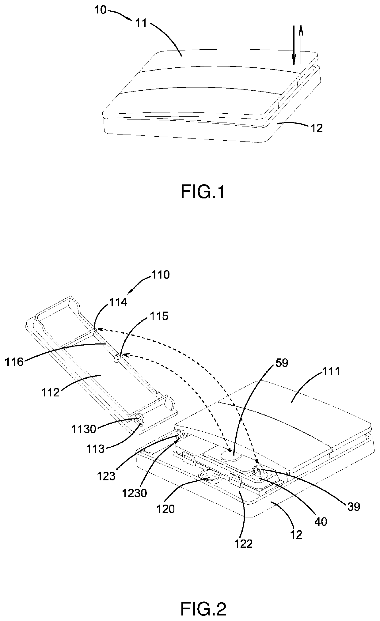
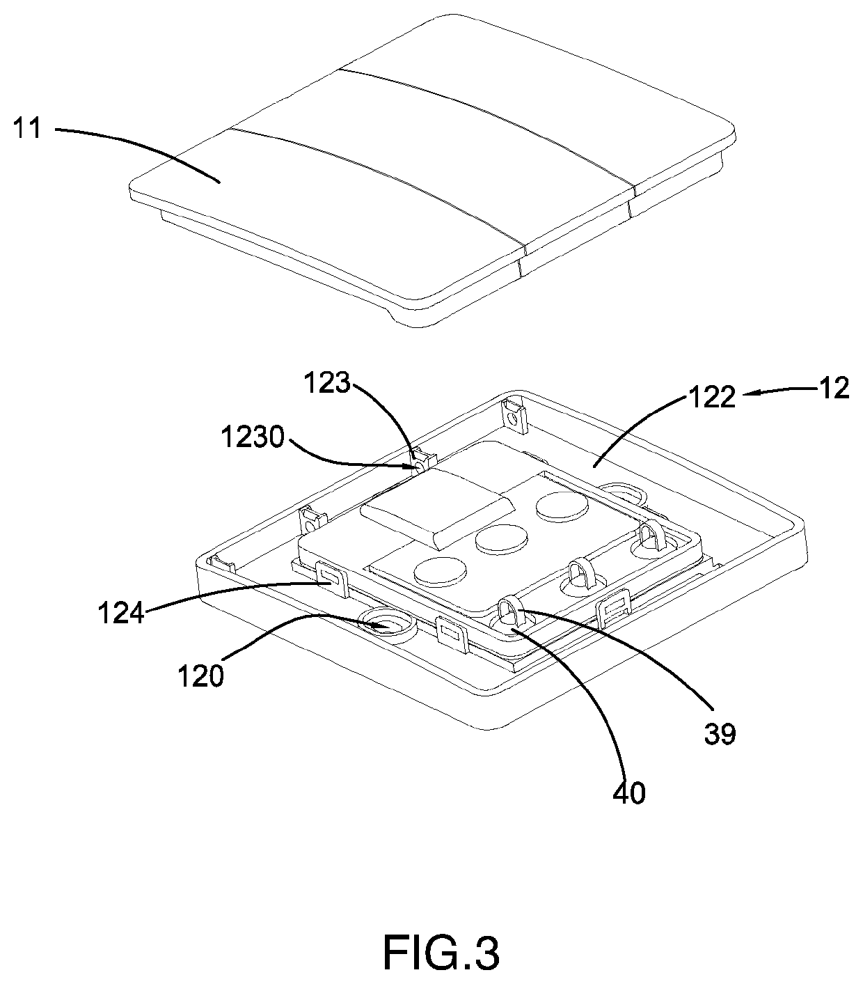
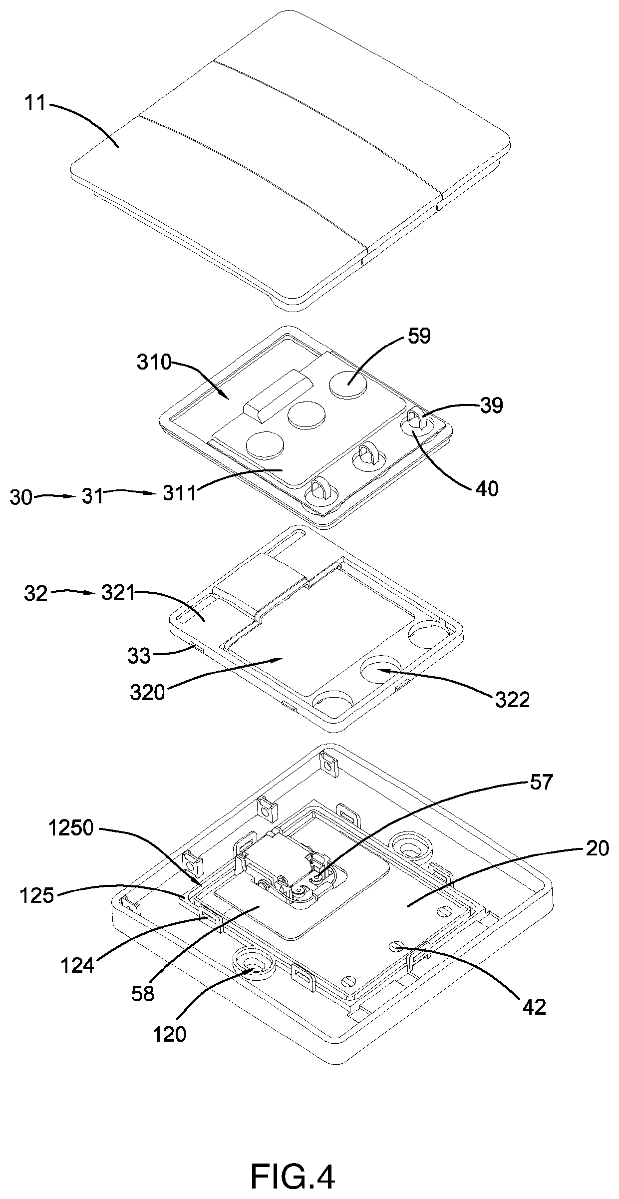
This patent describes a rebound switch that allows for easy customization of button configurations, reducing manufacturing and energy consumption requirements. The switch does not require any wiring, simplifying installation and increasing safety. It also reduces installation and utility costs, improving resource utilization. Additionally, the switch provides multiple rebounding buttons to independently control different light appliances, significantly reducing installation and utility costs of each lighting control loop. The size and installation method of the switch are standard, and it generates two consecutive electrical energies to maximize power output and improve control reliability.

Problems solved by technology

However, installing the conventional wall switch requires a pre-wiring system, wherein the wall switch is electrically connected to a power grid and an electric appliance, such as an electric lamp.
Accordingly, the labor cost is relatively high and the labor time is relatively long for installing the wiring system behind the wall surface.
In some cases, it is difficult to install the wiring system behind the hard surface, such as a tempered glass surface.
Furthermore, it is dangerous to install the wiring system in the buildings, especially long wires may cause fire or other accidents related to electrical problems.
The conventional wall switches cannot be used in wet or humid places such as bathrooms.
In other words, there are lots of unsafe factors for the conventional wall switches.
The existing passive wireless switches or powerless wireless switches are expensive even though the switches are able to control some smart appliances.
Due to the complexity of the mechanical design of the passive wireless switches, the cost thereof is relatively high, the reliability thereof is not high, and the practical application thereof is limited.
Accordingly, the existing rebound type passive wireless switch can only configure to have 2 buttons, such that it is difficult to control multiple electric appliances, such as multiple light appliances, in the building, unless multiple switches are installed.
However, increasing the number of switches will increase the cost.
Therefore, whether it is economical or practical view, the existing passive wireless switches cannot reach the level of traditional switches.
Therefore, the existing passive wireless switches are need to improve and are not popular to be used in the buildings.
In addition, whether it is the existing passive wireless switches or the traditional rebound type wall switches, the number of buttons is preset at the production and cannot be changed thereafter.
In fact, it is always a difference between the estimated quantity and the actual demand for the switch so as to cause the waste of material and labor cost.

Method used


Image

  • Passive Rebound Switch Having Variable Number of Buttons
  • Passive Rebound Switch Having Variable Number of Buttons
  • Passive Rebound Switch Having Variable Number of Buttons

Examples


Embodiment Construction

[0084]The following description is disclosed to enable any person skilled in the art to make and use the present invention. Preferred embodiments are provided in the following description only as examples and modifications will be apparent to those skilled in the art. The general principles defined in the following description would be applied to other embodiments, alternatives, modifications, equivalents, and applications without departing from the spirit and scope of the present invention.

[0085]It is appreciated that the terms “longitudinal”, “transverse”, “upper”, “lower”, “front”, “rear”, “left”, “right”, vertical“, “horizontal”, “top”, “bottom”, “exterior”, and “interior” in the following description refer to the orientation or positioning relationship in the accompanying drawings for easy understanding of the present invention without limiting the actual location or orientation of the present invention. Therefore, the above terms should not be an actual location limitation of ...


PUM


Abstract

A passive rebound switch includes an actuation button, an energy collecting module, a detection control, a housing, a power generation module, and a signal transmission circuit. The actuation button is detachably and pivotally connected to the housing. The power generation device, the signal transmission circuit, and the detection control are accommodated in an receiving chamber formed between the actuation button and the housing. When the actuation button is actuated to move in reciprocated rebounding movement, the energy collecting module is actuated to trigger the power generation module for converting mechanical energy into electrical energy to power the signal transmission circuit for transmitting a control signal. The energy collecting module is disposed between the actuation button and the power generation module. The detection switch pre-activates an I / O interface of an encoder device of the signal transmission circuit prior to the power generation module for generating the electrical power.

Description

CROSS REFERENCE OF RELATED APPLICATION[0001]This is a non-provisional application that claims priority to international application number PCT / CN2018 / 081072, international filing date Mar. 29, 2018, which claims priority to Chinese application number CN 201710213131.1, filing date Apr. 1, 2017, the entire contents of each of which are expressly incorporated herein by reference.NOTICE OF COPYRIGHT[0002]A portion of the disclosure of this patent document contains material which is subject to copyright protection. The copyright owner has no objection to any reproduction by anyone of the patent disclosure, as it appears in the United States Patent and Trademark Office patent files or records, but otherwise reserves all copyright rights whatsoever.BACKGROUND OF THE PRESENT INVENTIONField of Invention[0003]The present invention relates to electric switches, and more particularly to a passive rebound switch, which is able to be installed into a wall surface and selectively alter different ...

Claims


Application Information

Patent Timeline
IPC IPC(8): G08C17/02H01H21/24H01H21/08H02N2/18
CPCG08C17/02H01H21/08H02N2/18H01H21/24H05K5/0217H05K5/06G08C2201/112H01H2239/076H01H2300/03Y02B90/20Y04S20/14
Inventor LIU, YUANFANG
Owner GUANGDONG EBELONG INTELLIGENT TECH CO LTD
Learn More