
Flow rate control apparatus, flow rate control method, and program recording medium having recorded therein program for flow rate control apparatus

a flow rate control and flow rate control technology, applied in the direction of volume metering, process and machine control, instruments, etc., can solve the problem of greater pressure loss, and achieve the effect of less likely to affect robust control

Active Publication Date: 2020-01-23
HORIBA STEC CO LTD
View PDF0 Cites 2 Cited by
  • Summary
  • Abstract
  • Description
  • Claims
  • Application Information

AI Technical Summary

Benefits of technology

The present invention provides a flow rate control apparatus that can achieve high-speed flow rate control during certain times while maintaining a stable flow rate control point. The apparatus can handle changes in downstream valve openings and can reduce pressure loss even when multiple valves are used. This makes the flow rate control less affected by disturbances and ensures better control performance.

Problems solved by technology

However, because the above flow rate control apparatus includes not only the upstream valve but also the downstream valve, there is a problem that pressure loss becomes greater than a flow rate control apparatus including only one valve.

Method used


Image

  • Flow rate control apparatus, flow rate control method, and program recording medium having recorded therein program for flow rate control apparatus
  • Flow rate control apparatus, flow rate control method, and program recording medium having recorded therein program for flow rate control apparatus
  • Flow rate control apparatus, flow rate control method, and program recording medium having recorded therein program for flow rate control apparatus

Examples


first embodiment

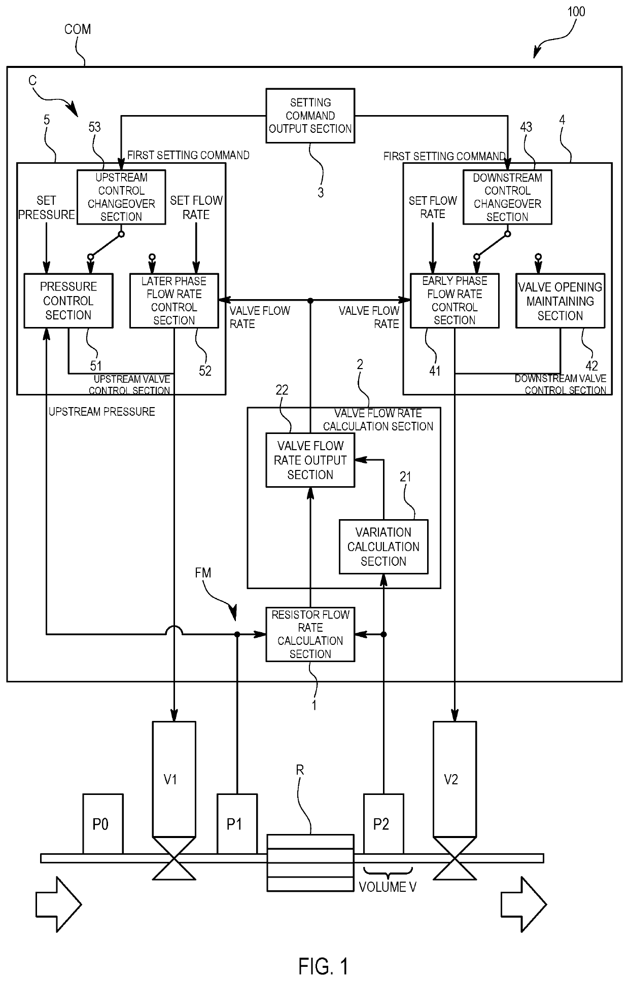
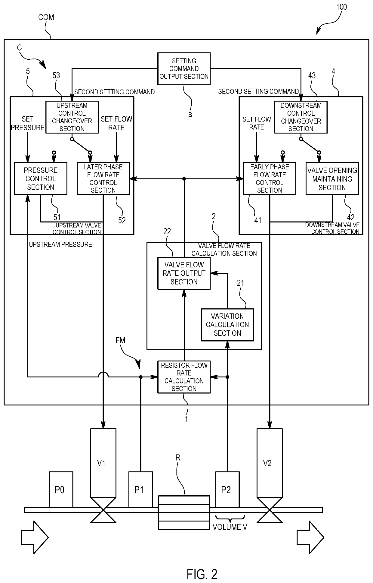
[0029]A flow rate control apparatus 100 in the present invention is described below with reference to the accompanying drawings.

[0030]The flow rate control apparatus 100 in the first embodiment is intended to be used for supplying gas that is a fluid into a chamber at a set flow rate in, for example, a semiconductor manufacturing process. The set flow rate is a step signal that causes stepwise rising or falling from a certain flow rate value to another flow rate value. A configuration is established so that a flow rate implemented by the flow rate control apparatus 100 follows the set flow rate within a predetermined period of time.

[0031]Specifically, the flow rate control apparatus 100 includes a fluid apparatus composed of a sensor and a valve disposed on a flow channel, and a control mechanism COM that handles control of the fluid apparatus as illustrated in FIGS. 1 and 2.

[0032]A supply pressure sensor P0, an upstream valve V1, an upstream pressure sensor P1, a fluid resistor R, ...

second embodiment

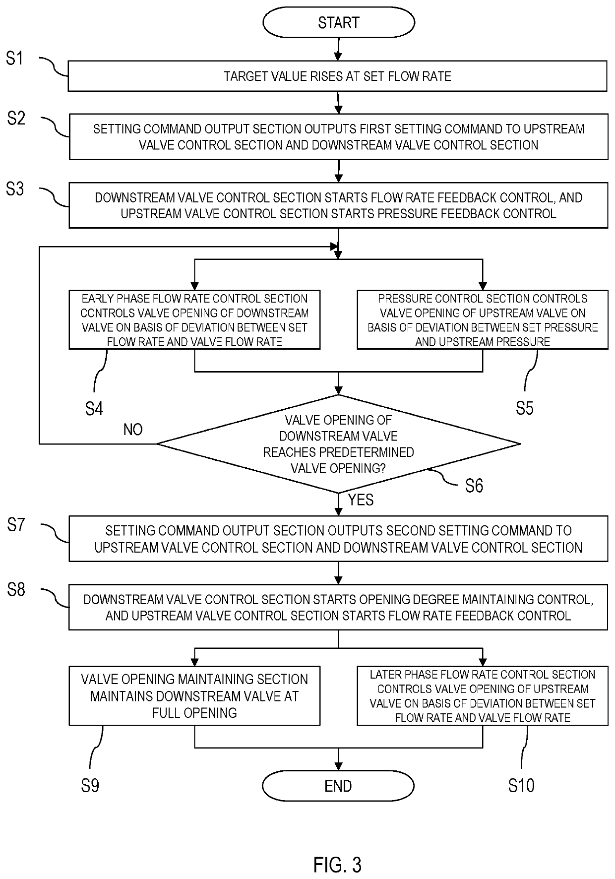
[0077]The flow rate control apparatus 100 in the second embodiment is designed so that the controller C controls the upstream valve V1 and the downstream valve V2 by using a deviation between a set flow rate and a resistor flow rate as a flow rate deviation. Specifically, when a valve opening of the downstream valve V2 is smaller than full opening that is a predetermined valve opening, the controller C inputs a resistor flow rate only to the early phase flow rate control section 41 so as to carry out flow rate feedback control by the downstream valve V2. When the downstream valve V2 reaches the full opening, the controller C inputs a resistor flow rate only to the later phase flow rate control section 52 so as to change over to flow rate feedback control by the upstream valve V1. The controller C includes a flow rate input changeover section 6 designed to change over flow rate feedback control by changing over an input destination to which the resistor flow rate is inputted, accordi...


PUM


Abstract

In order to provide a flow rate control apparatus capable of reducing pressure loss due to a downstream valve while enhancing responsiveness in flow rate control, a controller is designed to control the downstream valve on the basis of a flow rate deviation when a valve opening of the downstream valve is smaller than a predetermined valve opening. The controller is designed to control an upstream valve on the basis of the flow rate deviation when the valve opening of the downstream valve is the predetermined valve opening or more.

Description

BACKGROUND OF THE INVENTIONField of the Invention[0001]The present invention relates to a flow rate control apparatus including a plurality of valves.Background Art[0002]There has been a flow rate control apparatus including a flow rate sensor, an upstream valve disposed upstream of the flow rate sensor, and a downstream valve disposed downstream of the flow rate sensor as disclosed in Patent Document 1. With the flow rate control apparatus, a valve opening of the upstream valve is controlled on the basis of feedback of a measured pressure measured by a pressure sensor, and a valve opening of the downstream valve is controlled on the basis of feedback of a measured flow rate measured by the flow rate sensor.[0003]However, because the above flow rate control apparatus includes not only the upstream valve but also the downstream valve, there is a problem that pressure loss becomes greater than a flow rate control apparatus including only one valve.PRIOR ART DOCUMENTPatent Document[000...

Claims


Application Information

Patent Timeline
IPC IPC(8): G05D7/06G01F1/36G01F15/00
CPCG01F1/363G01F15/005G05D7/0623G05D7/0647G05D7/0635G05D16/028
Inventor NAGAI, KENTARO
Owner HORIBA STEC CO LTD
Learn More