
Tunnel mapping system and methods

a technology of tunnel mapping and tunnel, applied in surveying and navigation, navigation instruments, instruments, etc., can solve the problems of uncertainty in the clearance between train or subway cars and cable trays, geospatial location,

Active Publication Date: 2020-01-23
MASER CONSULTING INC
View PDF0 Cites 33 Cited by
  • Summary
  • Abstract
  • Description
  • Claims
  • Application Information

AI Technical Summary

Benefits of technology

The invention is a process to create highly accurate three-dimensional representations of objects in a space where GPS signals are not available or reliable. The process involves using a vehicle traveling in a tunnel on rails, along with a LiDAR, GPS, and inertial navigation system to determine the location of the vehicle. The vehicle then moves around the tunnel while the LiDAR produces point cloud datasets of the tunnel, which are adjusted based on the GPS, inertial navigation system, speed sensor, and precise measurements of rail coordinates to create a precise and accurate representation of the tunnel. The process can also include obtaining pre-defined tunnel geometry data and using it to further adjust the point cloud data sets. The invention addresses the difficulty of collecting accurate GPS data in spaces where it is not reliable.

Problems solved by technology

Although such systems work well to define the 3D models relative to the earth, there are problems associated in determining geospatial location in underground paths—such as rail or subway tunnels—where GPS signals cannot be received.
Without geospatially accurate and spatially representative information anywhere within the tunnel corridors, clearances between train or subway cars and cable trays may not be determined with confidence.

Method used


Image

  • Tunnel mapping system and methods
  • Tunnel mapping system and methods
  • Tunnel mapping system and methods

Examples


Embodiment Construction

[0018]The present invention will be described using an example of collecting geospatially accurate and spatially representative information within a rail or subway tunnel. It will be appreciated, however, that the present invention will be applicable to numerous other projects to gather such information where GPS signals are not available or reliable.

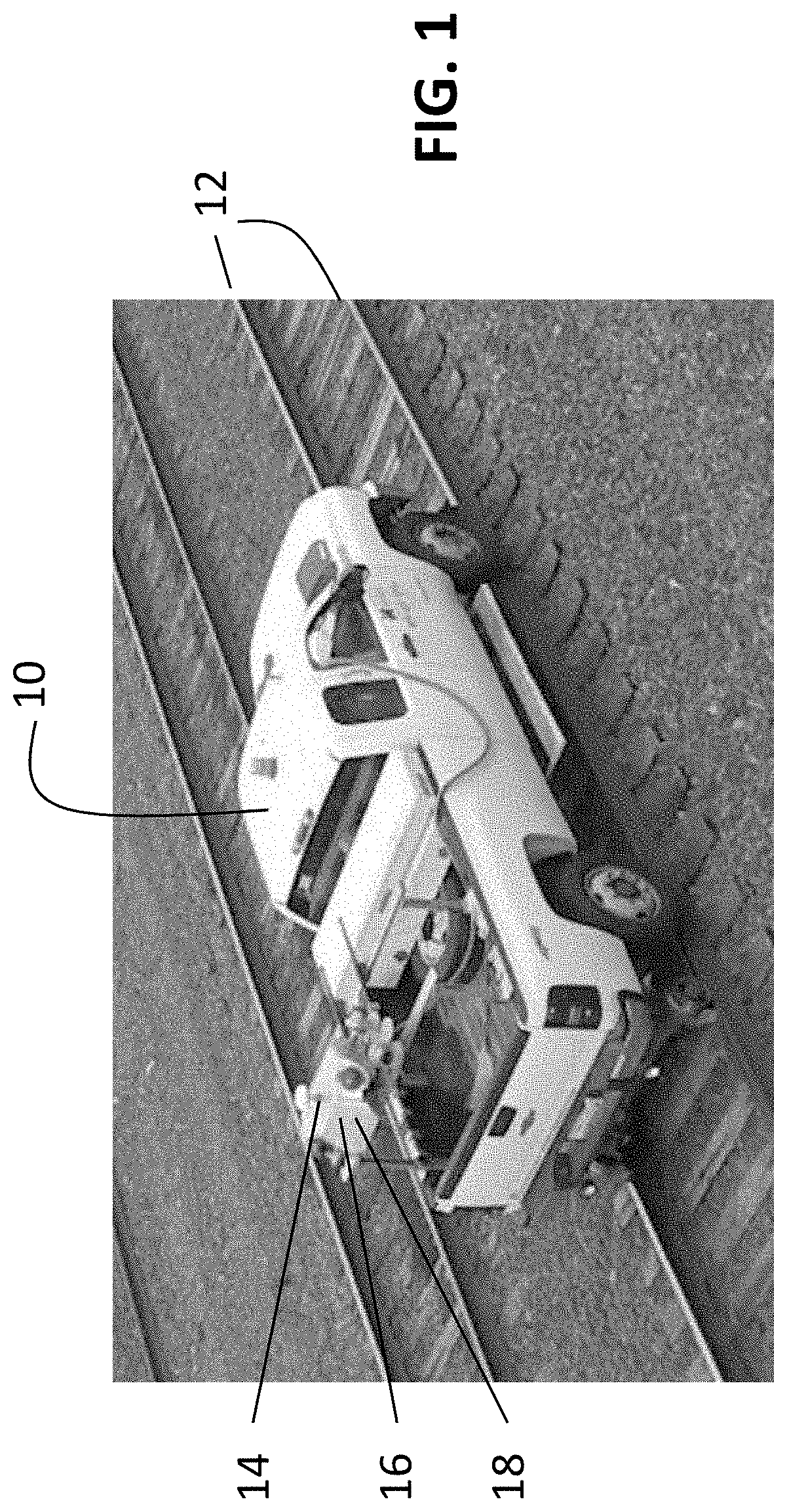
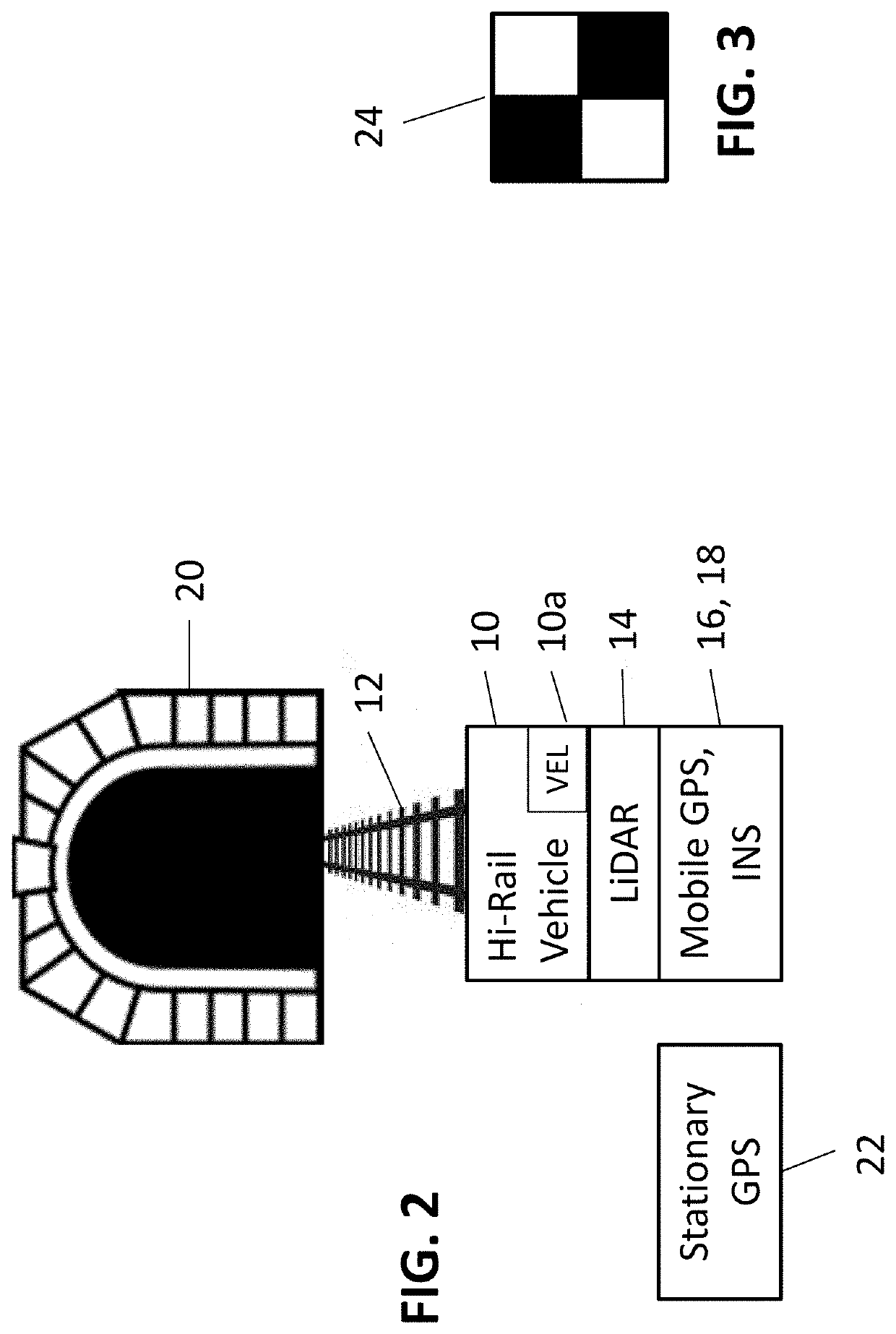
[0019]With reference to FIG. 1, a Hi-Rail vehicle 10 is placed on tracks 12. The Hi-Rail vehicle can operate both on rail tracks and a conventional road. When placed on the tracks, it can travel the path of interest. A LiDAR unit 14 is mounted on the vehicle at a precise position relative to the tracks 12. A GPS mobile unit 16 and an inertial navigation system (INS) 18 are also located on the vehicle at precise locations relative to the LiDAR unit. In operation, the Hi-Rail vehicle is driven along the path of interest to thereby produce mass point cloud datasets characterizing the scanned environment that can be managed, visualized and ...


PUM


Abstract

A process for constructing highly accurate three-dimensional mappings of objects along a rail tunnel in which GPS signal information is not available includes providing a vehicle for traversing the tunnel on the rails, locating on the vehicle a LiDAR unit, a mobile GPS unit, an inertial navigation system, and a speed sensor to determine the speed of said vehicle. A stationary GPS, whose geolocation is well-defined, is located near the entrance of the tunnel. Image-identifiable targets having a well-defined geodetic locations are located at preselected locations within the tunnel. The vehicle traverses the tunnel, producing mass point cloud datasets along said tunnel. Precise measurements of 3D rail coordinates are also obtained. The datasets are adjusted based on the mobile GPS unit, the inertial navigation system, the speed sensor, the location of the image-identifiable targets, and the precise measurements of 3D rail coordinates, to thereby produce highly accurate, and substantially geodetically correct, three-dimensional mappings of objects along the tunnel.

Description

[0001]The present application claims priority from U.S. Provisional Application Ser. No. 62 / 597,464, filed Dec. 12, 2017, the entire disclosure of which is hereby incorporated by reference.FIELD OF THE INVENTION[0002]The present invention is related to a tunnel mapping system and methods that provide precise mapping of underground transportation tunnels where global positioning system signals may not be available.BACKGROUND[0003]The precise mapping and characterization of ground transportation paths during construction and maintenance is required to insure operational safety of the public and maintenance personnel. For example, mapping along many miles of railroad track can be used for a variety of purposes, including track alignment, the development of 3D maps, clearance analysis, and future design. The data required for such activities can be acquired using Mobile LiDAR (light detection and ranging), a surveying method that measures distance to a target by illuminating the target ...

Claims


Application Information

Patent Timeline
Patent Type & Authority Applications(United States)
IPC IPC(8): G01C21/32G01S17/89G01S19/47
CPCG01S19/47G01S17/89G01C21/32G01S17/894G01S17/86G01S7/4817G01C7/06G01C21/3837G01C21/3848G01C21/383G01C21/1652G01S19/14G01S19/41G01S19/071
Inventor WYGANT, CLAY ALANDIGIACOBBE, PAULHULTQUIST, BRAD
Owner MASER CONSULTING INC
Learn More