
Magnetic coupling control device and magnetic coupling device

a control device and magnetic coupling technology, applied in the direction of dynamo-electric brakes/clutches, transportation and packaging, dynamo-electric components, etc., can solve the problems of nonlinear relationship between magnetic resistance and distance, increase production costs, complication of magnetic control methods, etc., and achieve accurate construction

Inactive Publication Date: 2020-01-02
CHENG HSI CHIEH
View PDF0 Cites 0 Cited by
  • Summary
  • Abstract
  • Description
  • Claims
  • Application Information

AI Technical Summary

Benefits of technology

The present invention provides a magnetic coupling control device that is structurally stable and allows for control and adjustment of the magnetic resistance force in a way that eliminates the problem of heat generation in the electromagnet. The device can output the energy of the flywheel rotation by magnetic coupling, and a fan module or power generating module can be attached to the rotating shaft to dissipate the heat generated by the device. The device includes a magnetoresistive ring frame that moves along the axial direction of the flywheel, and the overlapped area between the conducting inner ring frame and the first annular magnetic series on the flywheel results in a linear proportional relationship between the resistance force provided and the movement of the magnetoresistive ring frame, allowing for accurate control of the resistance.

Problems solved by technology

However, by adjusting the distance between the magnetic series and the flywheel to adjust the magnetic resistance, the relationship between the magnetic resistance and the distance is nonlinear.
This will lead to complication of the magnetic control method or an increase in production costs.
However, the electromagnet needs a considerable amount of power to generate magnetic force, causing heat generation of the electromagnet.
After a long use of the electromagnet, the high temperature will be difficult to dissipate.
Further, as flywheel rotates at a high speed, it is difficult to measure and control the temperature of the flywheel.
In addition, the temperature of the electromagnet also causes a magnetic drop, so the amount of power needs to be adjusted to make up the magnetic force.
This magnetic control design of using electromagnet to generate magnetic resistance is complicated, and difficult to control the precision.
Based on the above description, the conventional magnetic control unit still has drawbacks, which need to be improved.

Method used


Image

  • Magnetic coupling control device and magnetic coupling device
  • Magnetic coupling control device and magnetic coupling device
  • Magnetic coupling control device and magnetic coupling device

Examples


Embodiment Construction

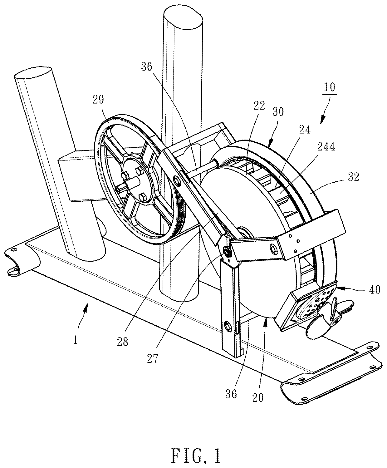
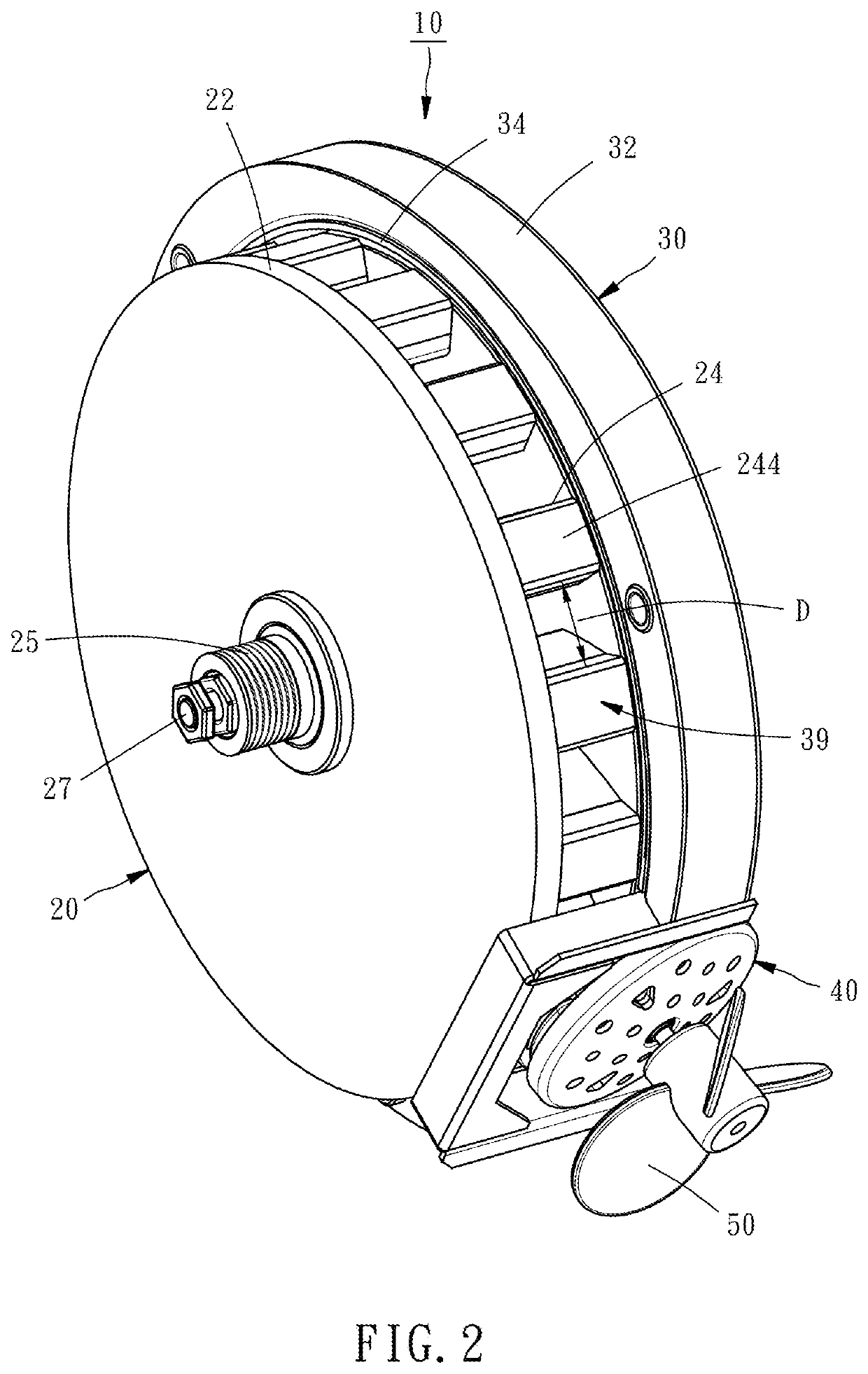
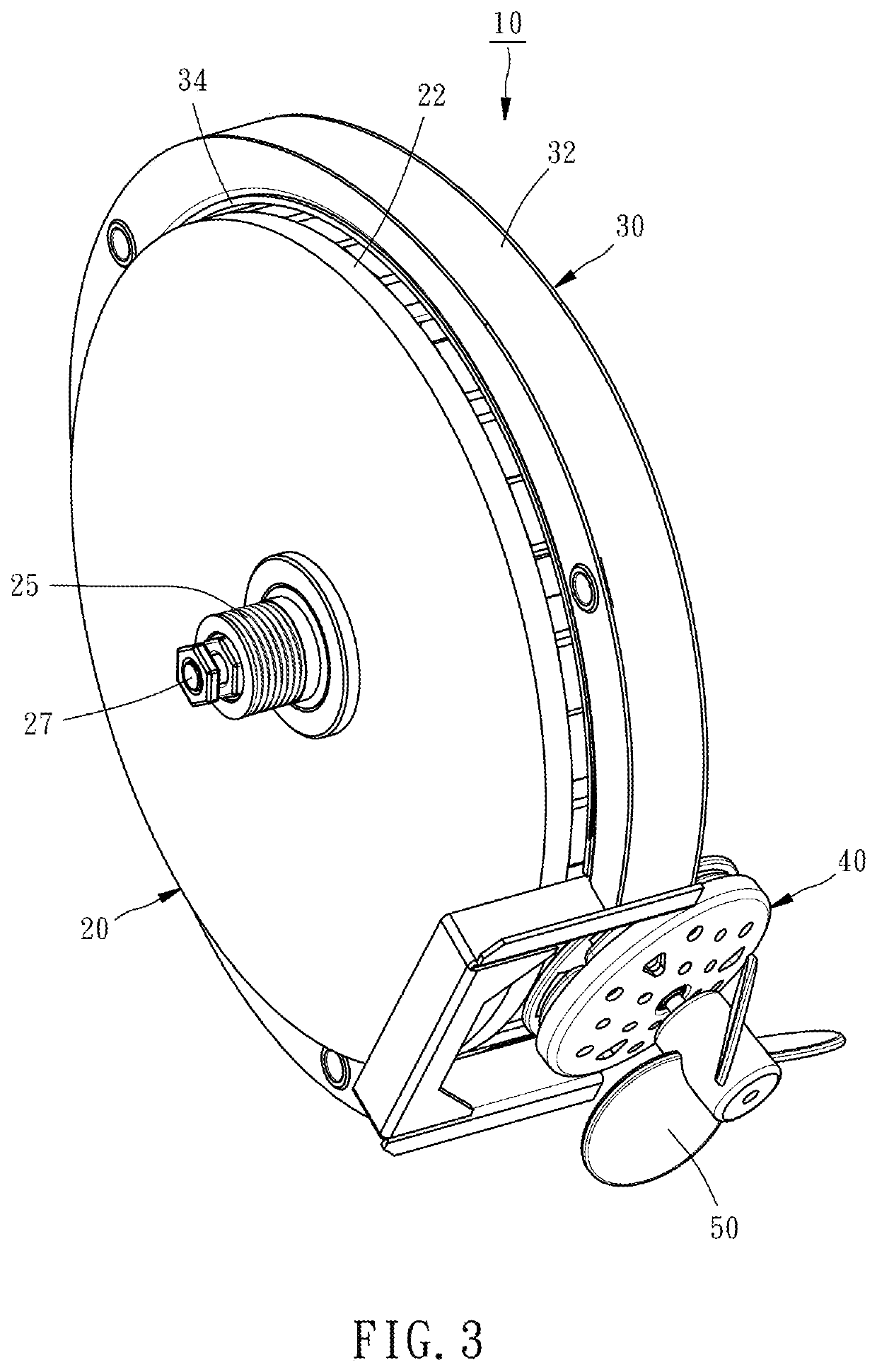
[0030]Referring to FIGS. 1-3, a magnetic coupling control device 10 in accordance with the present invention is used in an external machine 1. Preferably, the external machine 1 is a sports fitness equipment, for example, but not limited to, exercise bike. The magnetic coupling control device 10 comprises a magnetic flywheel unit 20, a magnetoresistive ring frame 30 and a magnetic coupling unit 40.

[0031]Referring to FIGS. 1-3, the magnetic flywheel unit 20 comprises a flywheel 22 and a plurality of first magnets 24. The flywheel 22 is shaped like a disc and mounted to the external machine 1. More to the point, an axle bushing 25 and an axle shaft 27 are provided at the center of axis of the flywheel 22. The axle bushing 25 is coaxially mounted at the center of axis of the flywheel 22 and synchronously rotatable with the flywheel 22. The axle shaft 27 is coaxially inserted through the axle bushing 25 and the flywheel 22 and mounted in the external machine 1 for allowing rotation of t...


PUM


Abstract

A magnetic coupling device includes a magnetic flywheel unit including a flywheel and multiple first magnets equiangularly spaced around the periphery of the flywheel to form a first annular magnetic series with the same pole facing toward the radial outer side of the flywheel, and a magnetic coupling unit including a plate body rotatably mounted to the periphery of the flywheel, a rotating shaft mounted to the center of axis of the plate body, multiple second magnets and third magnets alternatively mounted on the plate body around the rotating shaft to create a second annular magnetic series that is magnetically coupled to the first annular magnetic series. Further, a magnetoresistive ring frame is mounted to the periphery of the flywheel for movement along the axial direction of the flywheel to create a magnetic coupling control device.

Description

CROSS-REFERENCE TO RELATED APPLICATION[0001]This application is a continuation of U.S. patent application Ser. No. 15 / 858,235, filed Dec. 29, 2017.BACKGROUND OF THE INVENTION1. Field of the Invention[0002]The present invention relates to magnetic coupling technology and more particularly, to a magnetic coupling control device and a magnetic coupling device.2. Description of the Related Art[0003]Magneto-resistance device used in general fitness equipment (such as flywheel) is that a magnetic control unit is pivotably arranged on the outer edge or the inner edge of the flywheel. By adjusting the distance between the magnetic control unit and the flywheel, the resistance caused by the magnetic control unit on the flywheel is relatively adjusted. Taiwan Patent M512421 teaches installation of a pivoting member in an inner edge of a flywheel and mounting of a magnet on the pivoting member so that the magnetic resistance force can be adjusted by means of adjusting the distance between the ...

Claims


Application Information

Patent Timeline
Patent Type & Authority Applications(United States)
IPC IPC(8): H02K49/10
CPCH02K49/102H02K49/106H02K49/108Y02E60/16Y02T10/62
Inventor CHENG, HSI-CHIEH
Owner CHENG HSI CHIEH
Learn More