
Tunable waveguide system

a waveguide and tunable technology, applied in waveguide type devices, basic electric elements, antennas, etc., can solve the problems of difficult to achieve accurate tuning of electronic circuits for thz and/or submillimeterwave applications, parts have to be moved, and less accurate tuning, etc., to achieve accurate tunable waveguide

Active Publication Date: 2020-01-02
TOYOTA JIDOSHA KK +1
View PDF0 Cites 4 Cited by
  • Summary
  • Abstract
  • Description
  • Claims
  • Application Information

AI Technical Summary

Benefits of technology

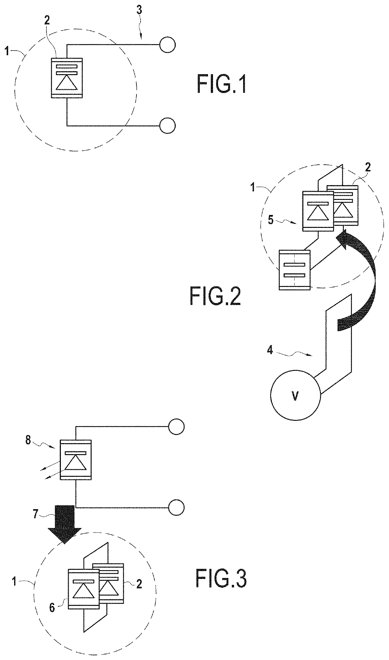
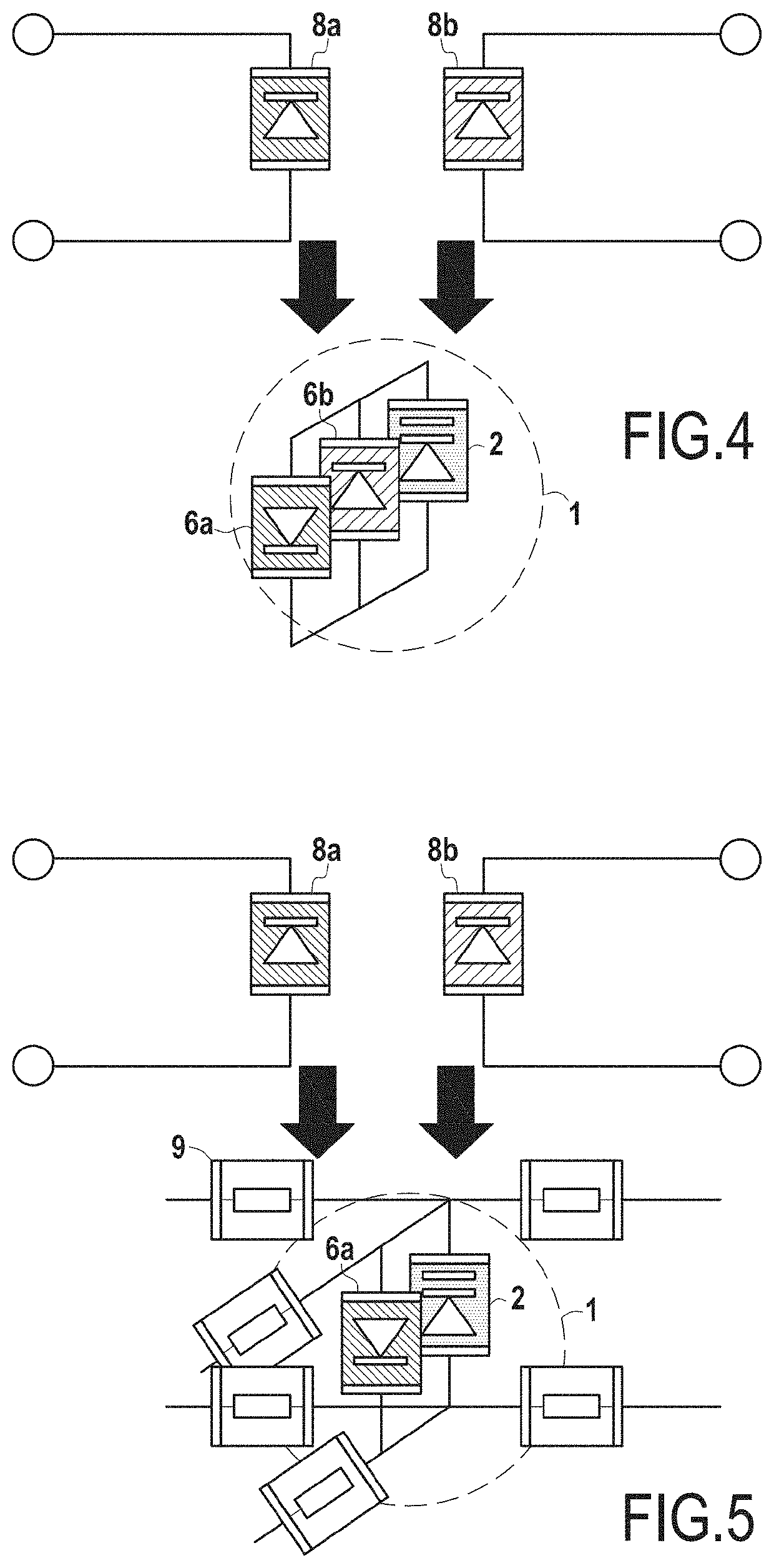
The present patent provides a tunable waveguide system that uses an electronically tunable metamaterial to manipulate radio waves in the THz and submillimeterwave ranges. The system includes a waveguide and a metamaterial that can change its electromagnetic characteristics by adding or removing bias voltage or by using photosensitive circuitry. The metamaterial can be programmed to process radio waves in a predetermined manner, such as by forming a spatial filter or a hologram. The system can also include a bias electronic circuit to apply a bias voltage to the non-linear elements. The patent also describes an antenna system and a radar antenna system that use the tunable waveguide system. The technical effects of the patent include providing an accurately tunable waveguide system that can be used for THz and submillimeterwave signal manipulation without the need for moving parts, and a method for tuning the waveguide system using a metamaterial.

Problems solved by technology

However, due to the mechanical tuning, parts have to be moved.
This leads to less accurate tuning, in particular accurate tuning of electronic circuits for THz and / or submillimeterwave applications becomes hardly feasible.

Method used


Image

  • Tunable waveguide system
  • Tunable waveguide system
  • Tunable waveguide system

Examples


Embodiment Construction

[0038]Reference will now be made in detail to exemplary embodiments of the disclosure, examples of which are illustrated in the accompanying drawings. Wherever possible, the same reference numbers will be used throughout the drawings to refer to the same or like parts.

[0039]In the present disclosure, nonlinear lumped elements may be added to a material and may be biased to change their dielectric properties. These changed properties may then be used to influence other electronics embedded or in contact with the material or to influence signals passing through the material.

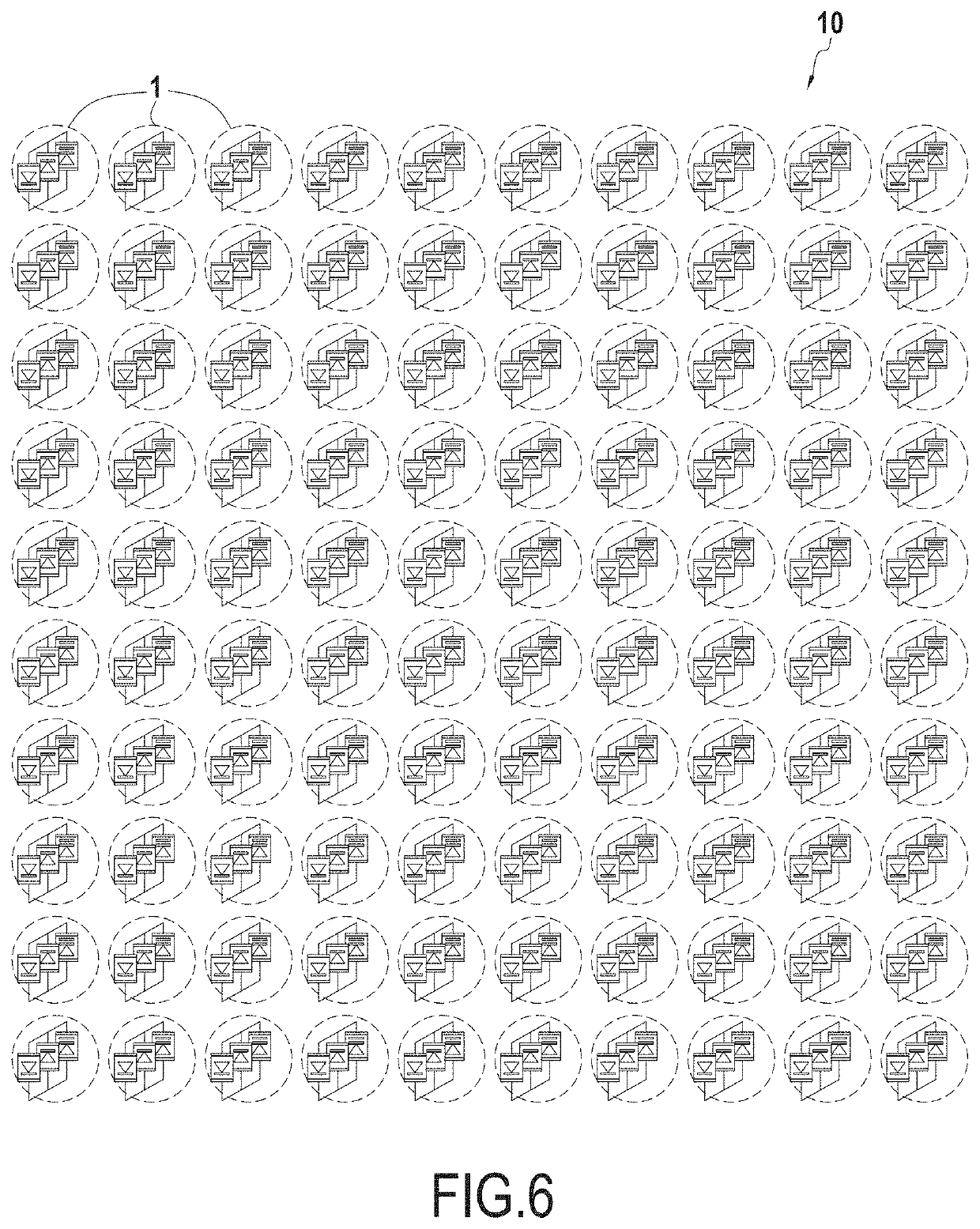
[0040]When adding said nonlinear elements at a density considerably smaller than the wavelength of operation, the overall dielectric behavior of the material may then be obtained by homogenization and the material exhibits anisotropic and uniform behavior.

[0041]Changing the bias voltage across the added nonlinear lumped elements, the dielectric function of the homogenized body may be changed. Having e.g. varactors ...


PUM

PropertyMeasurementUnit
dielectric constantaaaaaaaaaa
wavelengthaaaaaaaaaa

Abstract

The present disclosure relates to a tunable waveguide system comprising a waveguide configured to guide radio waves in at least two dimensions, and an electronically tunable metamaterial configured to tune the radio waves by electronically changing its dielectric and / or conductive characteristics. The present disclosure further relates to a radar antenna system.

Description

FIELD OF THE DISCLOSURE[0001]The present disclosure is related to a tunable waveguide system, in particular configured for a THz and / or submillimeterwave signal manipulation.BACKGROUND OF THE DISCLOSURE[0002]Tuning of waveguide circuits is done usually mechanically. However, due to the mechanical tuning, parts have to be moved. This leads to less accurate tuning, in particular accurate tuning of electronic circuits for THz and / or submillimeterwave applications becomes hardly feasible.[0003]There have been several approaches in the prior art regarding this issue.[0004]For example, WO 2001099224 A1 discloses electronically tunable dielectric composite thick films.[0005]U.S. Pat. No. 6,686,817 B2 refers to electronic tunable filters with dielectric varactors.[0006]U.S. Pat. No. 7,462,956 B2 discloses high efficiency NLTL comb generator using time domain waveform synthesis technique.[0007]U.S. Pat. No. 4,529,987 refers to a Broadband microstrip antennas with varactor diodes.SUMMARY OF T...

Claims


Application Information

Patent Timeline
Patent Type & Authority Applications(United States)
IPC IPC(8): H01Q15/00
CPCH01Q15/0086H01P1/00
Inventor OTHMEZOURI, GABRIELMERKEL, HARALD
Owner TOYOTA JIDOSHA KK
Learn More