Air-conditioning apparatus
a technology for air conditioning apparatus and air filter, which is applied in the direction of lighting and heating apparatus, heating types, instruments, etc., can solve the problems of inability to detect the presence of biofilms, inconvenient operation, and inability to clean up, so as to facilitate the determination of whether biofilms are present and prevent detection results.
- Summary
- Abstract
- Description
- Claims
- Application Information
AI Technical Summary
Benefits of technology
Problems solved by technology
Method used
Image
Examples
embodiment 1
100>
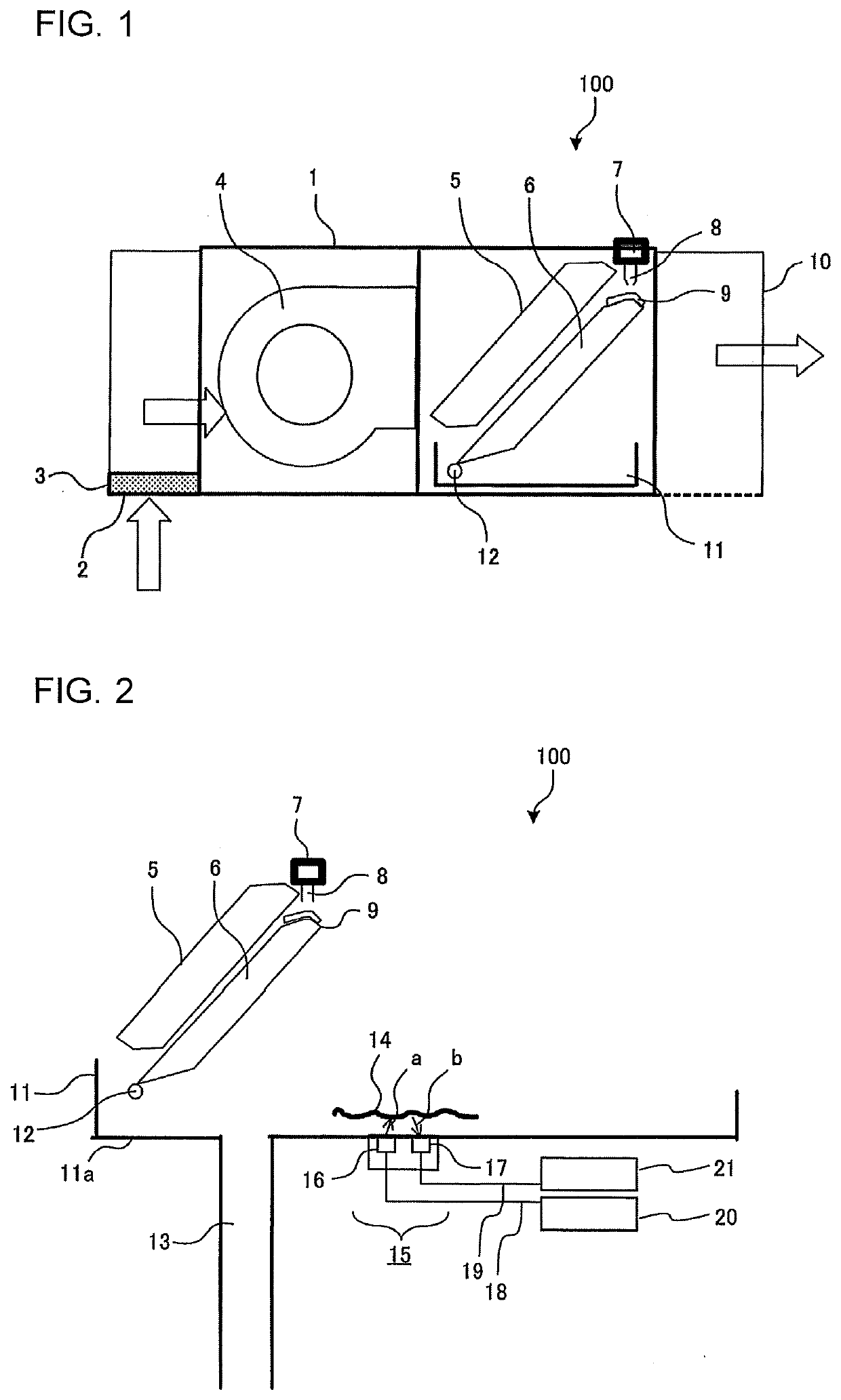
[0041]FIG. 1 is a schematic diagram of a cross-section of an air-conditioning apparatus 100 according to Embodiment 1. In FIG. 1, empty arrows indicate the direction of airflow. As illustrated in FIG. 1, the air-conditioning apparatus 100 according to Embodiment 1 includes the following components inside a housing 1: a fan 4, a heat exchanger 5, a humidifying material 6, a drain pan 11, and a supply unit 7 that supplies humidifying water used for humidification. The air-conditioning apparatus 100 has a cooling function, a heating function, and a humidifying function. An air inlet 2 that opens at the bottom of the housing 1 is provided on one lateral side of the casing 1. An air outlet 10 is provided on the other lateral side of the housing 1. As the fan 4 is driven, air is sucked into the air-conditioning apparatus 100 from the air inlet 2, and conditioned air that has passed through the heat exchanger 5 is blown out from the air outlet 10.
[0042]A filter 3 is placed over the air...
embodiment 2
[0089]FIG. 13 is a schematic diagram illustrating, in cross-section, a portion of an air-conditioning apparatus 102 according to Embodiment 2 in the vicinity of a drain pan 50. As illustrated in FIG. 13, the drain pan 50 according to Embodiment 2 differs from Embodiment 1 in that a drain pump 29 and a drain pipe 30 are provided to the drain pan 50. The drain pan 50 is used for, for example, places where it is difficult to drain out water naturally by gravity via the waste pipe 13 in the same manner as in Embodiment 1. Other features of the configuration according to Embodiment 2 are the same as Embodiment 1, and thus will not be described in further detail.
50>
[0090]The drain pump 29 is, for example, an electric pump with propeller. The drain pump 29 is disposed above the drain pan 50 to suck up the drain water 22 in the drain pan 50 from a suction port 29a. The drain pipe 30 is connected to the drain pump 29 to drain, to the outside, the drain water 22 sucked up by the drain pump 29...
embodiment 3
[0096]FIG. 15 is a schematic diagram illustrating, in cross-section, a portion of an air-conditioning apparatus 103 according to Embodiment 3 in the vicinity of a drain pan 51. As illustrated in FIG. 15, Embodiment 3 differs from Embodiments 1 and 2 in that the bottom surface of the drain pan 51 has a region that is sloped with respect to the horizontal plane with the lowest point being the position directly below the drain pump 29 disposed above the drain pan 51. Other features of Embodiment 3 are the same as Embodiments 1 and 2 and thus will not be described in further detail.
51>
[0097]The drain pan 51 is provided with the detection unit 15 disposed on the underside of the drain pan 51, the drain pump 29 disposed above the drain pan 51, and a sloped bottom surface. The horizontal level of the suction port 29a of the drain pump 29 is lower than the horizontal level of the ultrasound detector 17 of the detection unit 15.
103>
[0098]FIG. 16 is a schematic diagram illustrating, in cross-...
PUM
| Property | Measurement | Unit |
|---|---|---|
| frequency | aaaaa | aaaaa |
| frequency | aaaaa | aaaaa |
| frequency | aaaaa | aaaaa |
Abstract
Description
Claims
Application Information
 - R&D
- Intellectual Property
- Life Sciences
- Materials
- Tech Scout
- Unparalleled Data Quality
- Higher Quality Content
- 60% Fewer Hallucinations
Browse by: Latest US Patents, China's latest patents, Technical Efficacy Thesaurus, Application Domain, Technology Topic, Popular Technical Reports.
© 2025 PatSnap. All rights reserved.Legal|Privacy policy|Modern Slavery Act Transparency Statement|Sitemap|About US| Contact US: help@patsnap.com


