Wireless charging management system

a management system and wireless charging technology, applied in the direction of wireless communication, transmission, electric vehicles, etc., can solve the problems of inability to provide simple communication between charging spots and management servers, utilizing connectivity which is both expensive and complicated, and deployments cannot provide for user-charged devices

Active Publication Date: 2019-12-26
POWERMAT TECHNOLOGIES
View PDF0 Cites 1 Cited by
  • Summary
  • Abstract
  • Description
  • Claims
  • Application Information

AI Technical Summary

Benefits of technology

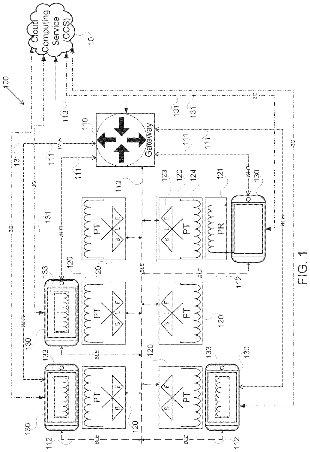
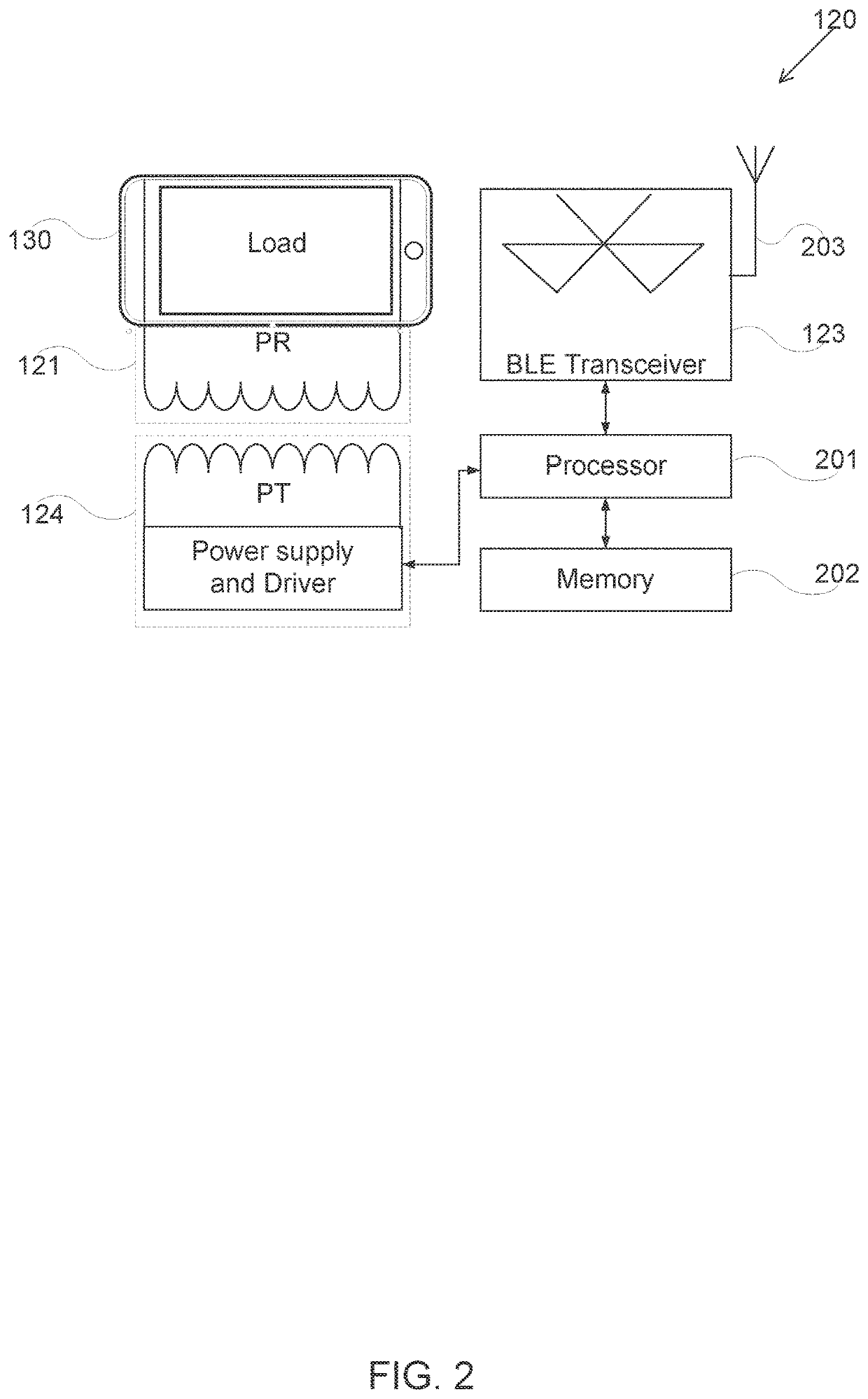
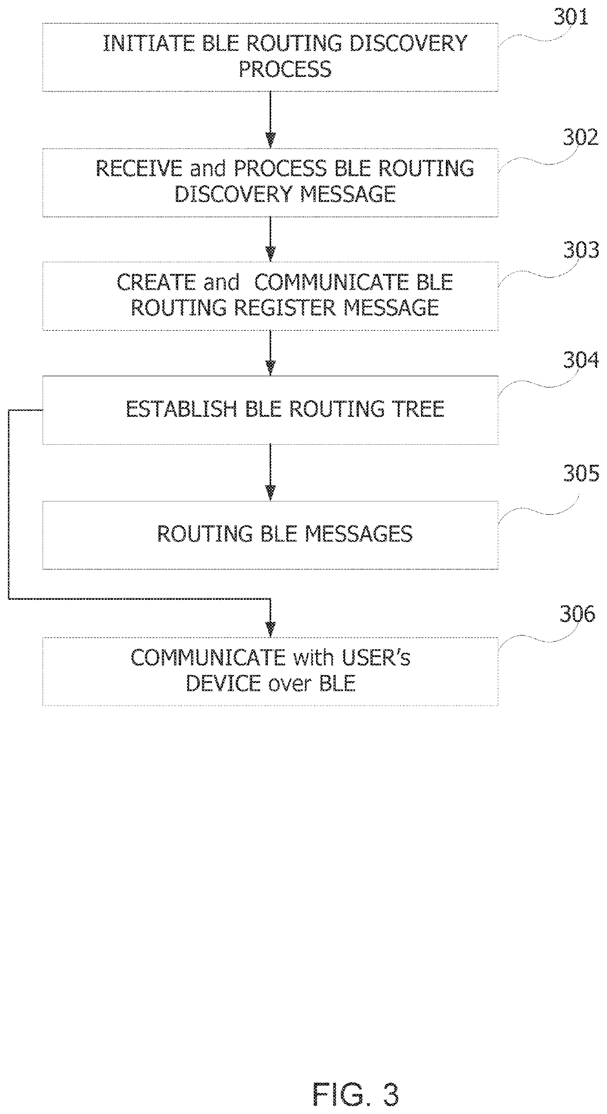
The present patent is about a system for managing inductive charging of devices using Bluetooth low energy (BLE) technology. The system includes a plurality of charging spots and a gateway, which can communicate with each other through BLE without pairing. The charging spots can be placed on devices and act as a relay for communication with the gateway. The gateway can communicate with the charging spots through BLE and act as a gateway for the devices in the venue. The system can provide services to the devices through the gateway, such as monitoring, configuration, control, and software upgrades. The charging spots can communicate with the devices either directly or through the gateway. The system can also support bidirectional communication between the charging spots and devices. The technical effects of the patent include improved convenience and efficiency for charging devices in a variety of settings.

Problems solved by technology

Currently, commercially available, systems are lacking proper communication between charging spots and management server.
In some of these deployments, the charging spots may be aggregated into a local area network (LAN), however utilizing connectivity which is both expensive and complicated.
Moreover, such commercially available deployments can't provide for simple communication of the charging spots with user charged devices.

Method used


Image

  • Wireless charging management system
  • Wireless charging management system
  • Wireless charging management system

Examples


Embodiment Construction

[0031]Before explaining at least one embodiment of the disclosed subject matter in detail, it is to be understood that the disclosed subject matter is not limited in its application to the details of construction and the arrangement of the components set forth in the following description or illustrated in the drawings. The disclosed subject matter is capable of other embodiments or of being practiced or carried out in various ways. Also, it is to be understood that the phraseology and terminology employed herein is for the purpose of description and should not be regarded as limiting. The drawings are generally not to scale. For clarity, non-essential elements were omitted from some of the drawings.

[0032]The terms “comprises”, “comprising”, “includes”, “including”, and “having” together with their conjugates mean “including but not limited to”. The term “consisting of” has the same meaning as “including and limited to”.

[0033]The term “consisting essentially of” means that the compo...


PUM


Abstract

According to a first aspect of the present disclosed subject matter, a system for managing inductive charging of at least one device, the system comprising: at least one venue comprising: a plurality of charging spots each of which comprises a dedicated Bluetooth low energy (BLE) transceiver designed to enable communication between charging spots of the plurality of charging spots, wherein at least one charging spot of the plurality of charging spots is capable of being configured as a relay; at least one gateway comprising a BLE transceiver; wherein the gateway is capable of communicating, by its BLE transceiver, with each charging spot either directly or indirectly via the relay; and a cloud computing server configured to provide services to the at least one venue; and wherein the CCS is connected with at least one venue via the Internet.

Description

TECHNICAL FIELD[0001]The present disclosed subject matter relates to wireless power charging systems. More particularly, the present disclosed subject matter relates to remote management of a plurality of wireless power charging-spots.BACKGROUND[0002]Growing demand for wireless power charging, led to dramatic deployments increase, in a wide variety of venues, raises the need for effective remote management. Typically, a deployment of each venue consists of a plurality of charging-spots that are partially connected to one another. To maintain the expected services, allow or alter monetization options for each deployed infrastructure, software update, user authentication, or the like; some centralized management servers are needed. Currently, commercially available, systems are lacking proper communication between charging spots and management server. Such communication is needed to implement a conditional charging service for allowing charged devices that identify themselves and incl...

Claims


Application Information

Patent Timeline
IPC IPC(8): H02J7/02H02J50/80H02J50/10H04B5/00
CPCH04B5/0075H04L67/10H04B5/0037H04W88/16H02J50/80H02J7/025H02J50/10H04W40/00H02J7/0044H04B5/24H04B5/79
Inventor SHERMAN, ITAYSALHUV, AMIR
Owner POWERMAT TECHNOLOGIES
Why Eureka
Try Eureka